AIXTRON - Dokumentation CONFIDENTIAL 57
3
crius_II_en_00, Edition 06/2010
System Manual Description
CRIUS II Process technology
3.1.2 System principle
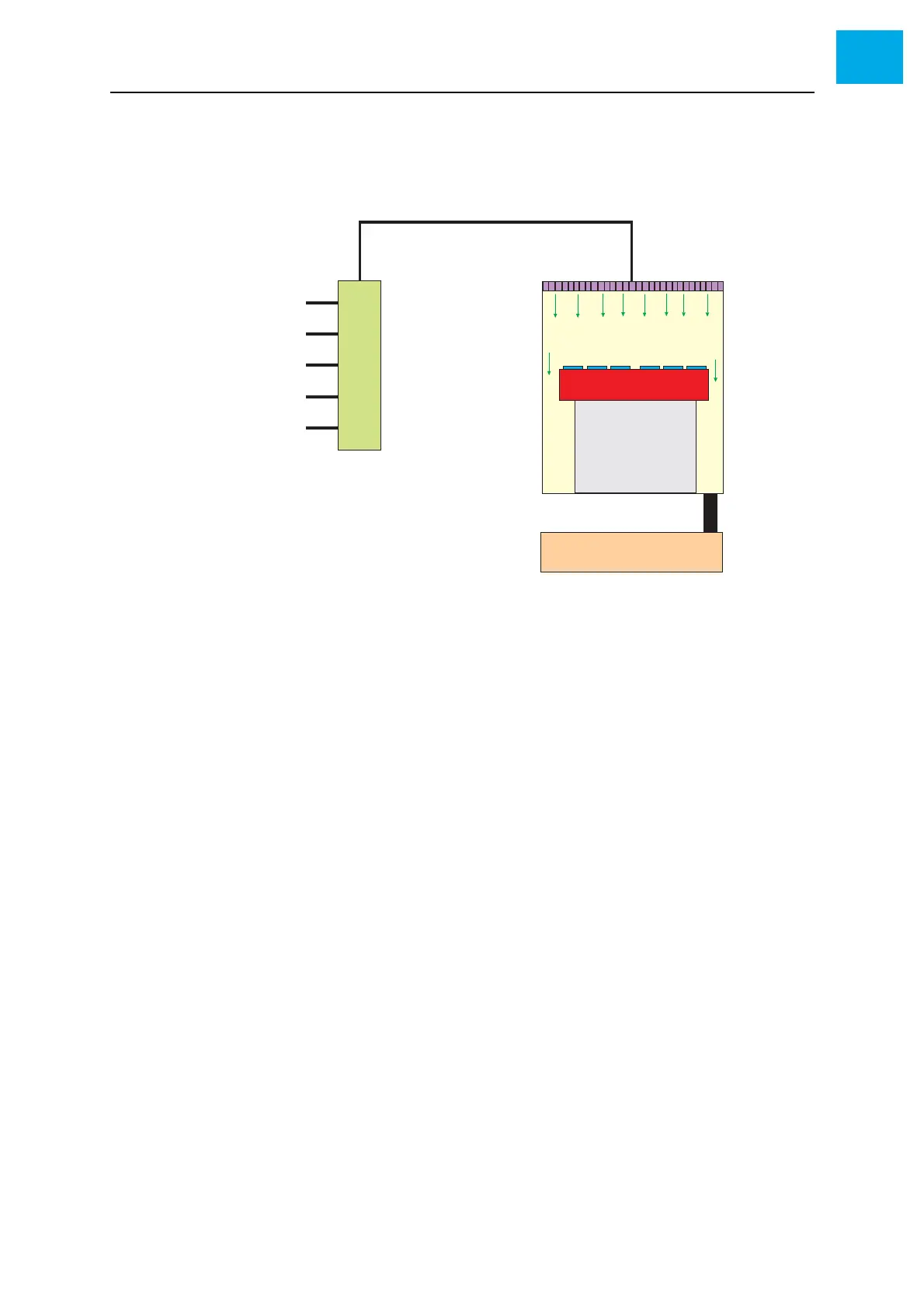
Fig. 3-2, 57 schematically illustrates the design of a CVD system.
Fig. 3-2 Schematic design of a CVD system
During a CVD process, the following steps are performed:
1 The process gases (item A) are mixed in the gas mixing system (item B)
2 The process gases are fed via the showerhead (item C) into the reactor
(item D)
3 A coating is deposited on the heated substrates (item E)
Because a CVD process is usually performed at low pressure, the reactor is
connected to a pump system (item H).
A Process gas supply
B Gas mixing system
C Showerhead
D Reactor chamber
ESubstrate(s)
F Susceptor
G Heating
H Pump system