crius_II_en_00, Edition 06/2010
80 CONFIDENTIAL AIXTRON - Dokumentation
Description System Manual
Gas system CRIUS II
3
3.6.6 Controlling and measuring components
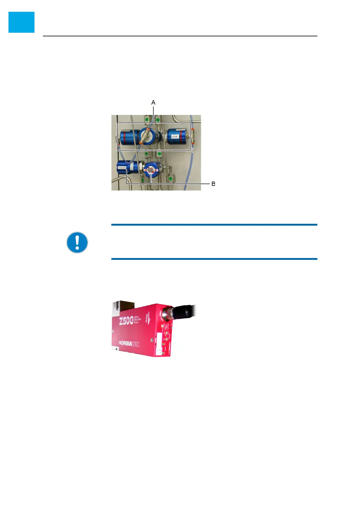
Valves
As an example, Fig. 3-28, 80 shows the arrangement of valves installed
before a standard MO source.
Fig. 3-28 Valves (example)
A 4/2-way valve
B Manual valves
Pressure and flow controllers
Fig. 3-29, 80 shows a digital flow controller. The pressure controllers look
like the flow controllers.
Fig. 3-29 Flow controller (MFC)
NOTE:
An «H» indicates valves that switch hazardous gases.