AIXTRON - Dokumentation CONFIDENTIAL 71
3
crius_II_en_00, Edition 06/2010
System Manual Description
CRIUS II Gas system
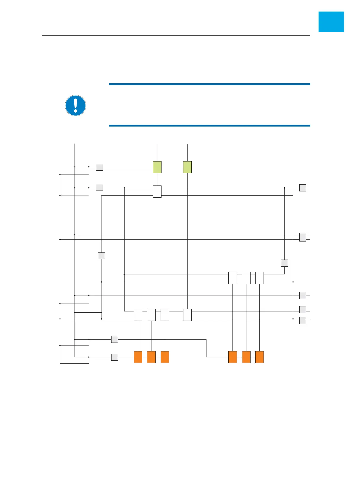
3.6.1 Gas diagram
Fig. 3-20, 71 shows a simplified gas diagram of a CRIUS II.
Fig. 3-20 Gas diagram (example)
NOTE:
The figure shown below relates to a typical CRIUS II.
Your specific system may differ from this in certain details. Always refer
to the delivered gas diagram.
A Hydride gases
B Gas supply for hydride sources
C Gas supply for run lines
D Gas dosing unit for hydride source
E Pneumatic 5/2-way valve
F Hydride run line (lower plenum)
G Purge Panel
H MO2 run line (upper plenum)
I Bypass for MO run line
J MO1 run line (upper plenum)
K Vent line
L Gas supply for vent lines
M Gas supply for MO2 sources
N Gas supply for MO1 sources
O MO bubbler
N
2
H
2
D
B
E
OO OO
A
F
E
EEE
E
L
C
G
M
O
O
E
E
D
A
I
J
H
K
N