AIXTRON - Dokumentation CONFIDENTIAL 79
3
crius_II_en_00, Edition 06/2010
System Manual Description
CRIUS II Gas system
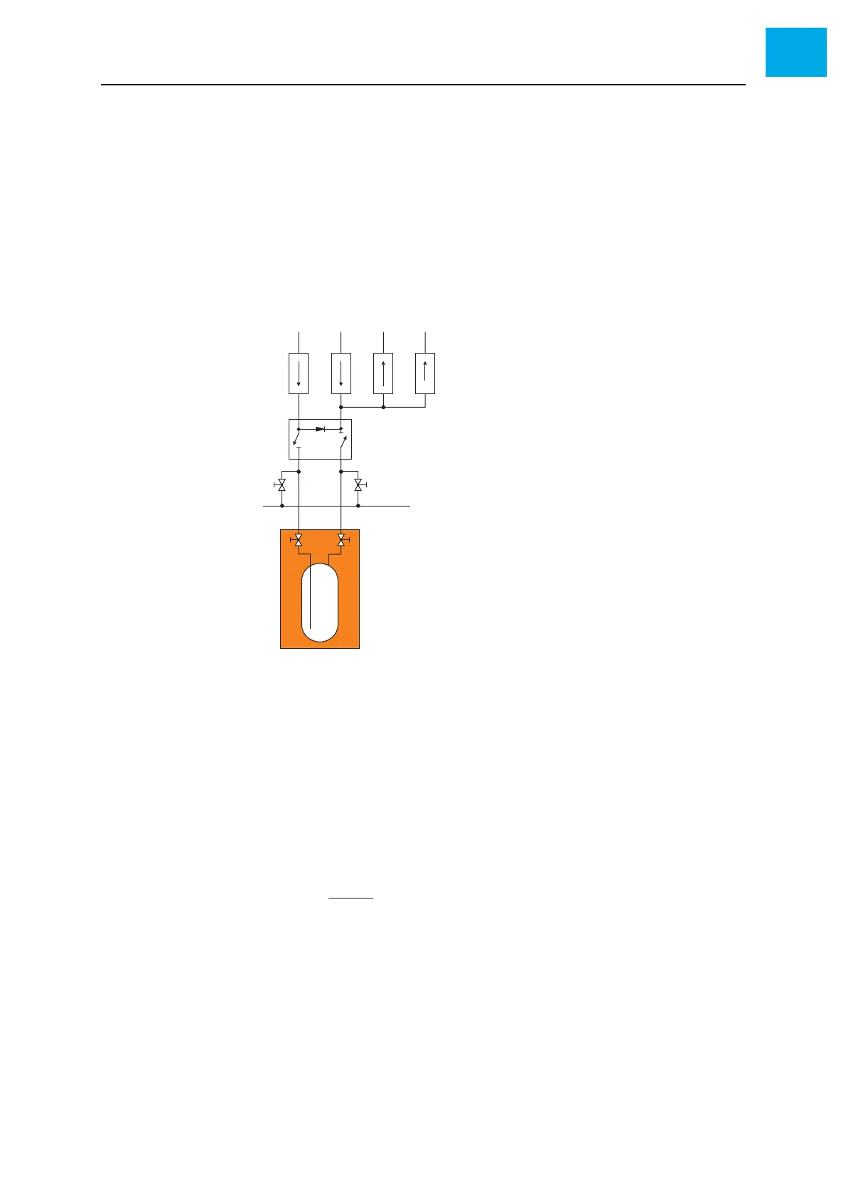
Doping MO source The doping MO source is used if the process requires low gas flows or a large
flow range. Fig. 3-27, 79 shows the gas diagram for the doping MO source.
The source MFC (item D) and the dilute MFC (item E) adjust the MO concen-
tration in the carrier gas. It is fed via the inject MFC (item F) into the MO
run/vent line.
The pressure controller (item G) controls the pressure operating point for the
inject MFC (item F) and leads away excess gas into the hydride vent line (item
C).
Fig. 3-27 Doping MO source
Provided that all MFCs are in the control range, you can use the following for-
mula to calculate the process gas flow F
R
into the reactor:
F
1
= flow through the source MFC
F
2
= flow through the dilute MFC
F
3
= flow through the inject MFC
AH
2
supply
B To MO run/vent line
C To MO vent line
D Source MFC
E Dilute MFC
FInject MFC
G Pressure controller
H 4/2-way MO source valve
I Quarter turn manual valve
J MO vacuum (for changing the MO bubbler)
K Manual valve at the bubbler
L Thermostat heat bath
M MO bubbler