Chapter 4 INTERFACE SETTINGS
107
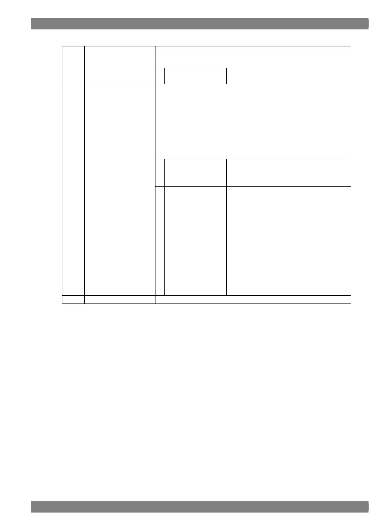
<DVI unit setting parameters>
This sets On or Off for each channel.
The same settings as the ones described in “4.1.1 Setting the output
interfaces to ON or OFF” can also be established.
0
Off
No output.
(1)
Output 1ch (0/1)
Output 2ch (0/1)
1
On
Output.
This sets the bit length and link format of the images to be output from DVI. A
setting which is independent of the bit length for pattern drawing can be
selected. It is also possible to select the bit length automatically. The portion
by which the bit length for pattern drawing exceeds the bit length which has
been set here is discarded. A deficient portion is filled with zeros.
“Single” can be selected when the dot clock frequency ranges from 25 MHz
to 165 MHz, and data can be output from output channels 1 and 2.
“Dual” can be selected when the dot clock frequency ranges from 50 MHz to
330 MHz, and data can be output from output channel 1. Data is not output
from channel 2.
“4.1.5 Setting the bit length (gray scale) for pattern drawing”
0
Single (8 bits)
The data is output by Single Link from output
channels 1 and 2. The portion by which the bit
length for pattern drawing exceeds 8 bits is
discarded.
1
Dual (8 bits)
The data is output by Dual Link from output
channel 1. The portion by which the bit length for
pattern drawing exceeds 8 bits is discarded.
Data is not output from channel 2.
2
Single (16 bits)
Up to 16 bits are output by Single Link using the
two links of output channel 1. The portion by
which the bit length for pattern drawing is
deficient from the bit length which has been set
here is filled with zeros.
The data is output by Single Link from output
channels 2. The portion by which the bit length
for pattern drawing exceeds 8 bits is discarded.
(2)
Mode (0/1)
3
Single (Auto)
The data is output by Single Link from output
channels 1 and 2. Single (8 bits) or Single (16
bits) is automatically selected depending on the
bit length for pattern drawing.
(3)
CTL0/CTL1
This is not normally used. Keep it at the low setting.
 Loading...