Chapter 4 INTERFACE SETTINGS
57
4.2 HDMI
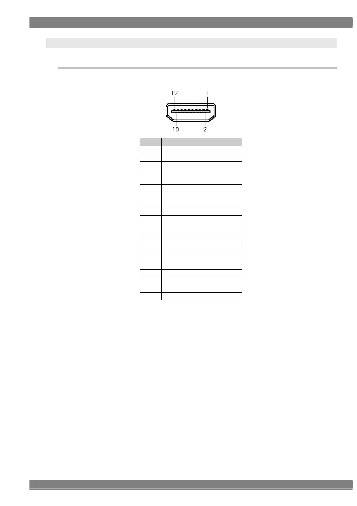
4.2.1 Connectors and pin assignments
HDMI
Pin no. Signal
1 TMDS DATA2+
2 TMDS DATA2 SHIELD
3 TMDS DATA2-
4 TMDS DATA1+
5 TMDS DATA1 SHIELD
6 TMDS DATA1-
7 TMDS DATA0+
8 TMDS DATA0 SHIELD
9 TMDS DATA0-
10 TMDS CLK+
11 TMDS CLK SHIELD
12 TMDS CLK-
13 CEC
14 RESERVE / HEAC+
15 DDC CLK
16 DDC DATA
17 GROUND (for +5 V)
18 +5 V (DDC power supply *1)
19 HOT PLUG DETECT / HEAC-
Shell FG
*1: Restrictions apply to the supply current of the DDC power supply. Refer to “12.3 Concerning the
maximum current consumption of the DDC (DP_PWR) power supply.”
 Loading...