Chapter 4 INTERFACE SETTINGS
163
4.5.4 Bit arrays
Bit arrays has the following kinds; SAMPLE1 (DISM standard), SAMPLE2 (OpenLDI standard) and
USER (1 to 3) which can be set by users.
For the setting procedure, refer to “4.5.2 LVDS setting procedure.”
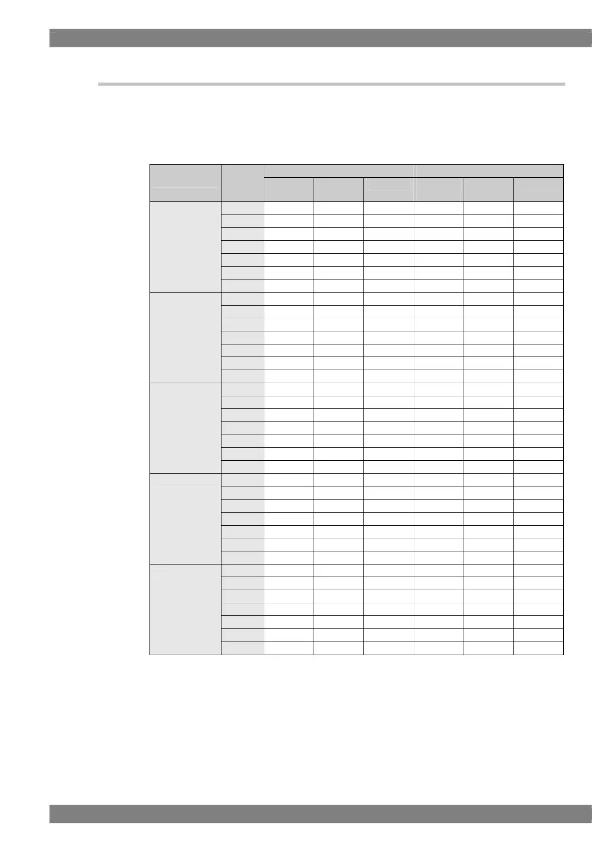
Bit arrays for 8 to 10 bits for using one output connector
8-bit mode 10-bit mode
Operation
signal
Data No.
SAMPLE1
(DISM)
SAMPLE2
(OpenLDI)
USER SAMPLE1
(DISM)
SAMPLE2
(OpenLDI)
USER
TA0 R2 R0 R (X) R4 R0 R (X)
TA1 R3 R1 R (X) R5 R1 R (X)
TA2 R4 R2 R (X) R6 R2 R (X)
TA3 R5 R3 R (X) R7 R3 R (X)
TA4 R6 R4 R (X) R8 R4 R (X)
TA5 R7 R5 R (X) R9 R5 R (X)
TA
TA6 G2 G0 G (X) G4 G0 G (X)
TB0 G3 G1 G (X) G5 G1 G (X)
TB1 G4 G2 G (X) G6 G2 G (X)
TB2 G5 G3 G (X) G7 G3 G (X)
TB3 G6 G4 G (X) G8 G4 G (X)
TB4 G7 G5 G (X) G9 G5 G (X)
TB5 B2 B0 B (X) B4 B0 B (X)
TB
TB6 B3 B1 B (X) B5 B1 B (X)
TC0 B4 B2 B (X) B6 B2 B (X)
TC1 B5 B3 B (X) B7 B3 B (X)
TC2 B6 B4 B (X) B8 B4 B (X)
TC3 B7 B5 B (X) B9 B5 B (X)
TC4 HS HS HS HS HS HS
TC5 VS VS VS VS VS VS
TC
TC6 DE DE DE DE DE DE
TD0 R0 R6 R (X) R2 R6 R (X)
TD1 R1 R7 R (X) R3 R7 R (X)
TD2 G0 G6 G (X) G2 G6 G (X)
TD3 G1 G7 G (X) G3 G7 G (X)
TD4 B0 B6 B (X) B2 B6 B (X)
TD5 B1 B7 B (X) B3 B7 B (X)
TD
TD6 L L L L L L
TE0 L L L R0 R8 R (X)
TE1 L L L R1 R9 R (X)
TE2 L L L G0 G8 G (X)
TE3 L L L G1 G9 G (X)
TE4 L L L B0 B8 B (X)
TE5 L L L B1 B9 B (X)
TE
TE6 L L L L L L
* In the 9-bit mode, the lowest bit of 10-bit mode is discarded and placed to upward.
 Loading...