Chapter 4 INTERFACE SETTINGS
89
4.2.11 Audio Return Channel
On this screen, the Audio Return Channel function is executed, and the patterns of the related data are
displayed.
The sound received is output from the COAX digital audio output connector.
* This function is supported only by the HDMI 1.4a unit (VM-1822) and HDMI 300MHz unit(VM-1823).
It is not supported by the VM-1817 HDMI Unit.
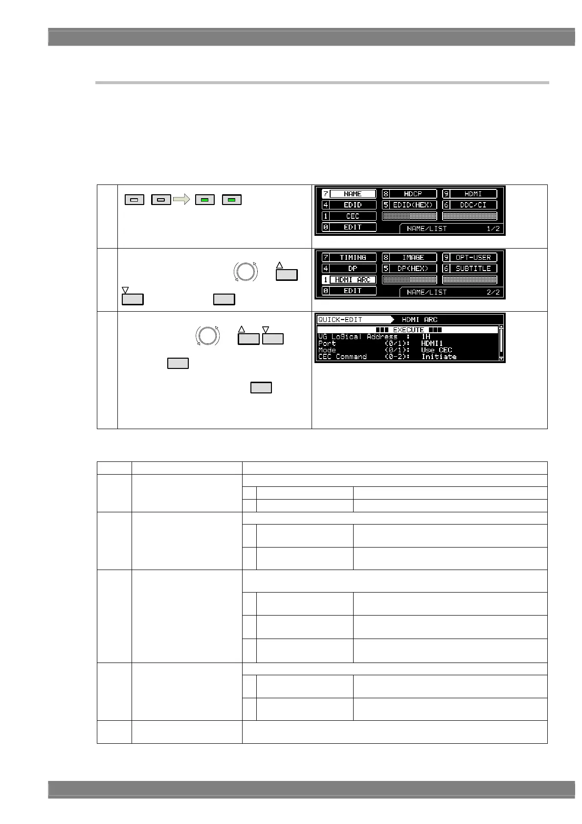
<Audio Return Channel display procedure>
(1)
NAME/LIST
DETAIL
NAME/LIST
DETAIL
(2)
<Selecting the HDMI ARC>
Select the HDMI ARC using
or
INC
DEC
, and then press
SET
.
(3)
<Detailed setting: Selecting EDIT>
Select EDIT using
or
INC
DEC
, and
then press
SET
.
Alternatively, select EDIT using
0/STATUS
.
After the setting items have been edited, select
EXECUTE, and press the SET key to enable the
settings.
<Table of Audio Return Channel setting items>
(1)
VG Logical Address
This sets the logical address of the VG generator. (0 to F)
This sets the port used for Audio Return Channel execution.
0
HDMI1
Audio Return Channel is executed using HDMI1.
(2)
Port (0/1)
1
HDMI2
Audio Return Channel is executed using HDMI2.
This sets the operation mode.
0
Use CEC
ARC start and end are controlled using the CEC
commands.
(3)
Mode (0/1)
1
Audio Monitor
The sound acquisition is started without using
the CEC commands.
These set the operation to be performed when CEC (0) has been selected
as the Mode setting.
0
Wait Request
Operation which accords with the ARC start and
end requests from ARC TX is performed.
1
Initiate
ARC is started from ARC RX (VG).
(The “Initiate ARC” command is sent.)
(4)
CEC Command (0-2)
2
Terminate
ARC is ended from ARC RX (VG).
(The “Terminate ARC” command is sent.)
This sets the send destination of the CEC commands.
0
Auto
The commands are sent to the adjoining device
of the generator. *
(5)
Follower: Mode (0/1)
1
Manual
A logical address is specified, and the
commands are sent to this address.
(6)
Follower: LogicalAddr
This sets the logical address where the commands are to be sent when
Manual (1) has been selected as the Follower: Mode setting. (0-F)
 Loading...