456
10.6 Adjustments
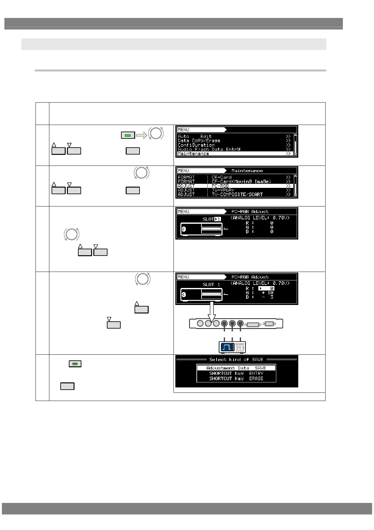
10.6.1 Adjusting the RGB video levels of the PC analog unit
The RGB video levels of the PC analog unit will be adjusted in this section.
After adjusting the levels, save the data.
(1) Display the raster ‘white’ pattern (No.1121) using any timing data.
Check that the digital levels are the maximum values. (Refer to “4.1.8 Setting the digital level.”)
Set the analog levels to the desired values. (Refer to “4.7.2 Setting the analog output connectors”)
(2)
Select Maintenance using
MENU
or
INC
DEC
, and then press
SET
.
(3)
Select ADJUST: PC-RGB using
or
INC
DEC
, and then press
SET
.
(4) <Where there is a multiple number of PC
analog units>
Use
to select “SLOT.”
Then use
INC
DEC
to select the number of
the slot which contains the unit whose levels are
to be adjusted.
↑
Display representing generator’s rear panel
(5)
Select “R,” “G” and “B” using
.
While monitoring the actual level on an
oscilloscope or other measuring device, adjust
to the value set in step (1) using
INC
(to
increase the level) or
DEC
(to reduce the
level).
* Perform the step for “R,” “G” and “B.”
PCアナログユニット
GBR
オシロスコープ
(6)
Press
SAVE
.
Then select “Adjustment Data SAVE” followed
by
SET
.
After ‘Save Completed’ has appeared, operation returns to the screen in step (5).
Oscilloscope
PC analog unit
 Loading...