10
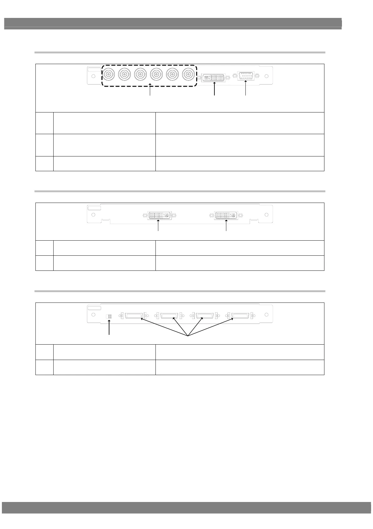
1.5.3 PC analog unit (VM-1811)
DVI-I
VGA
CS VS HS B/P G/Y R/P
BR
PC
(17)(16)
(15)
For details on connectors (7) and (9), refer to the descriptions of the DVI unit and TV encoder unit, respectively.
(15) Analog component output connectors
Either RGB signals or color difference signals (YPbPr/YCpCr) can
be selected and output here.
H/V separate sync and CS (composite sync) can be output.
(16) DVI-I output connector Digital or analog signals can be output from this connector.
(DVI-I connector)
HDCP is supported. (Dual-Link is not supported.)
(17) VGA output connector
Analog component signals (RGBHV) can be output as separate
H/V sync signals here. (Shrink Dsub 15-pin connector)
1.5.4 DVI unit (VM-1814)
DVI-D 2 DVI- D 1
DVI
(6)(7)
(6) DVI-D output connector Only digital signals can be output here. (DVI-D connector)
Dual-Link is supported. (HDCP is not supported.)
(7) DVI-D output connector Only Digital signals can be output here. (DVI-D connector)
HDCP is supported. (Dual-Link is not supported.)
1.5.5 LVDS unit (VM-1815)
LV D S 4 LV D S 3 LVDS 2 LV DS 1
5V
DDC
3.3V
LV D S
(18)(19)
(18) LVDS output connectors The signals of four 10-bit systems can be output here.
DISM or OpenLDI can be selected.
(19) (DDC power supply selector switch) This switch is not normally used.
It can select the supply voltage when DDC is used.
 Loading...