Chapter 4 INTERFACE SETTINGS
171
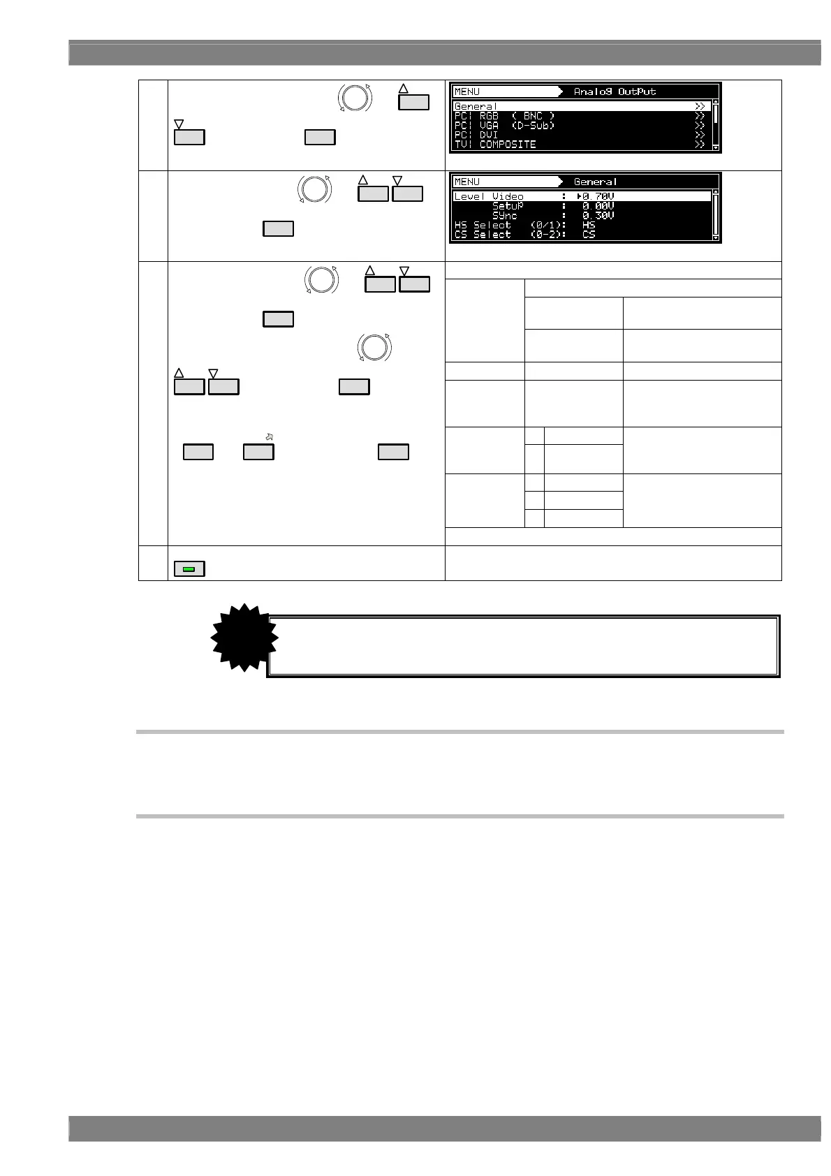
(3)
Select Analog Output using
or
INC
DEC
, and then press
SET
.
(4)
Select General using
or
INC
DEC
,
and then press
SET
.
The parameters are set here.
The video level is set here.
0.05-1.20 V
Video-On-Sync is in the off
state.
Video
0.30-1.20 V
Video-On-Sync is in the on
state.
Setup
0.00-0.25 V The setup level is set here.
Sync
0.00 to 0.60 V
The sync signal
(Video-On-Sync) level is
set here.
0HS
HS Select
1CS
The signal to be output
from the HS connector is
selected here.
0CS
1HS
CS Select
2 VS
The signal to be output
from the CS connector is
selected here.
(5)
Select the items using
or
INC
DEC
,
and then press
SET
.
Set the numerical values using or
INC
DEC
, and then press
SET
.
Alternatively:
Make the selections using the number keys
(
0/STATUS
to
9/F
), and then press
SET
.
MENU
Display returns to the initial screen.
4.7.3 Setting the analog video level
For details on changing the analog video level, refer to “4.1.7 Setting the analog level.”
4.7.4 Sync signal settings
For further details on the sync signal ON/OFF settings and polarity settings, refer to “4.1.2 Setting the
sync signals to ON or OFF and setting the sync signal polarities.”
Set within the range of [Video ≥ Setup] and [Video ≥ Sync] and [Video ≥ (Setup +
Sync)].
CAUTION
 Loading...