Chapter 4 INTERFACE SETTINGS
145
4.5 LVDS
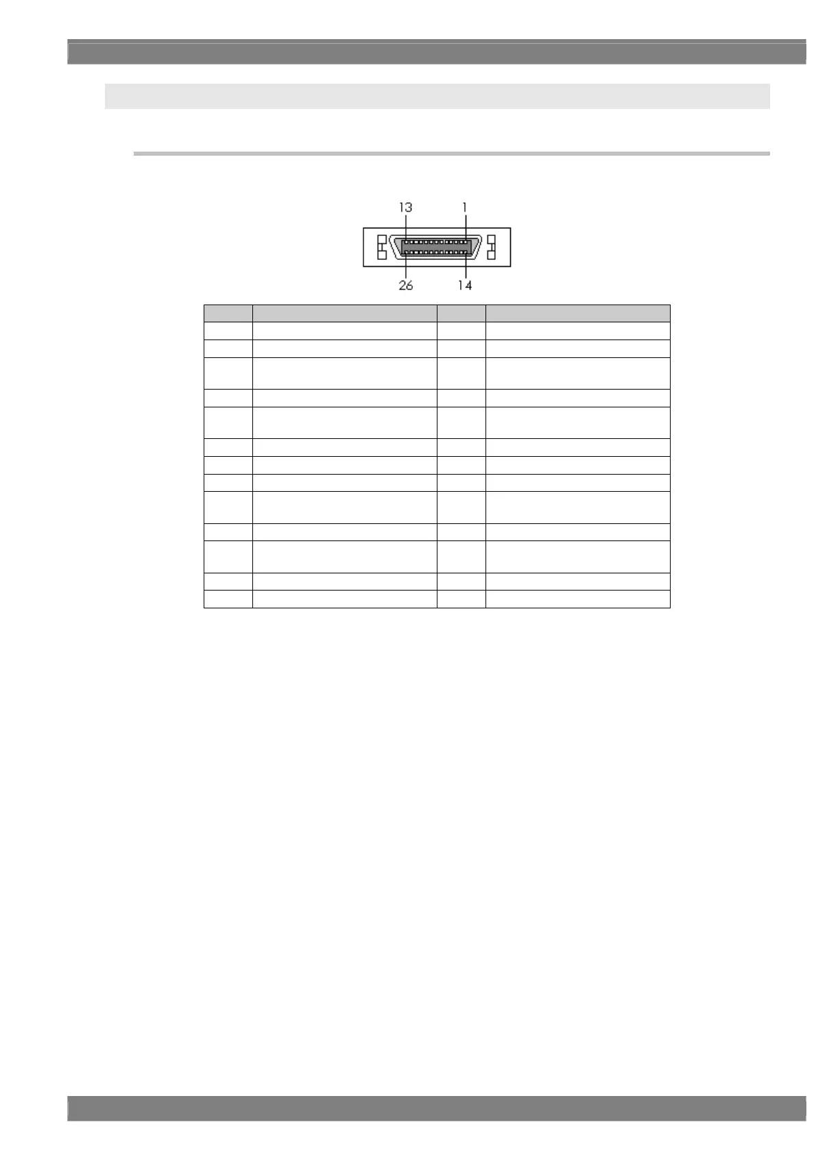
4.5.1 Connectors and pin assignments
Connector: MDR 10226-1210-VE made by 3M
Pin no. Signal Pin no. Signal
1 GND 14 TA-
2 TAG 15 TA+
3
Reserve
(leave this unconnected)
16 GND
4 TB- 17 TBG
5 TB+ 18
Reserve
(leave this unconnected)
6 TC- 19 TCG
7 TC+ 20 TE-
8 TEG 21 TE+
9
Reserve
(leave this unconnected)
22 TCLK-
10 TCLKG 23 TCLK+
11
+5 V/+3.3 V
(DDC power supply *1)
24
+5 V/+3.3 V
(DDC power supply *1)
12 TD- 25 TDG
13 TD+ 26 GND
*1: Restrictions apply to the supply current of the DDC power supply. Refer to “12.3 Concerning the
maximum current consumption of the DDC (DP_PWR) power supply.”
 Loading...