150
4.5.3 Data transfer system
Settings (1) to (6) in the table below are available as the data transfer system settings.
Item Description Output from other units
Setting (1) What is drawn is output as is. (Same output for channels 1 to 4) ON
Setting (2)
The data is output dot by dot to channels 1 and 2. (Same output
for channels 3 and 4)
ON
Setting (3) The data is output dot by dot to channels 1, 3, 2 and 4. ON
Setting (4)
The left half of the screen is output to channel 1, and the right
half of the screen is output to channel 2. (Same output for
channels 3 and 4)
OFF
Setting (5)
One-fourth of the screen each is output to channels 1, 3, 2 and 4
in this order.
OFF
Setting (6)
The left half of the screen is output to channels 1 and 3, and the
right half of the screen is output to channels 2 and 4.
OFF
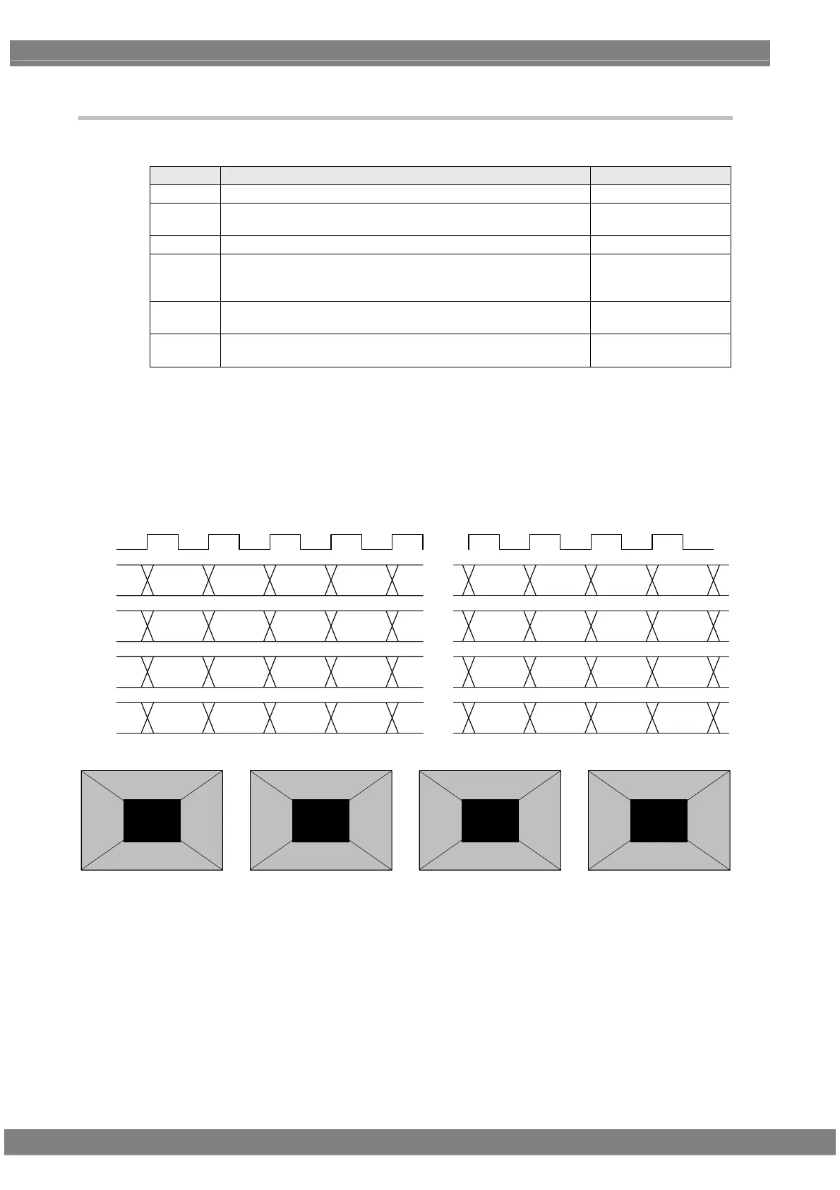
<Specifications for outputs of 8 to 10 bits>
Setting (1) [Single (10 bits)], [Normal]
The same image is output to all four channels. The output level is 8 to 10 bits.
The example is that the resolution is 1280 × 1024, the dot clock frequency is 108 MHz, with the 10 bits output.
D 0
[9:0]
D 1 D 2 D 3
・・・
・・・
[9:0] [9:0] [9:0]
D 1276
[9:0]
D 1277 D 1278 D 1279
[9:0] [9:0] [9:0]
CLK
108MHz
D 0
[9:0]
D 1 D 2 D 3
・・・
[9:0] [9:0] [9:0]
D 1276
[9:0]
D 1277 D 1278 D 1279
[9:0] [9:0] [9:0]
D 0
[9:0]
D 1 D 2 D 3
・・・
[9:0] [9:0] [9:0]
D 1276
[9:0]
D 1277 D 1278 D 1279
[9:0] [9:0] [9:0]
D 0
[9:0]
D 1 D 2 D 3
・・・
[9:0] [9:0] [9:0]
D 1276
[9:0]
D 1277 D 1278 D 1279
[9:0] [9:0] [9:0]
1CH
2CH
3CH
4CH
1CH 2CH 3CH 4CH
 Loading...