Chapter 4 INTERFACE SETTINGS
113
4.4 4K2K (iTMDS, iTMDS Quad) (VM-1824, VM-1824-A)
The specifications differ for each of the connectors so refer to the table below.
Unit/connector Dual-Link HDCP Analog
iTMDS unit (VM1824) 1CH
- -
iTMDS unit (VM1824) 2CH
- -
iTMDS Quad unit (VM1824-A)
1CH
- - -
iTMDS Quad unit (VM1824-A)
2CH
- - -
iTMDS Quad unit (VM1824-A)
3CH
- - -
iTMDS Quad unit (VM1824-A) 4CH
- - -
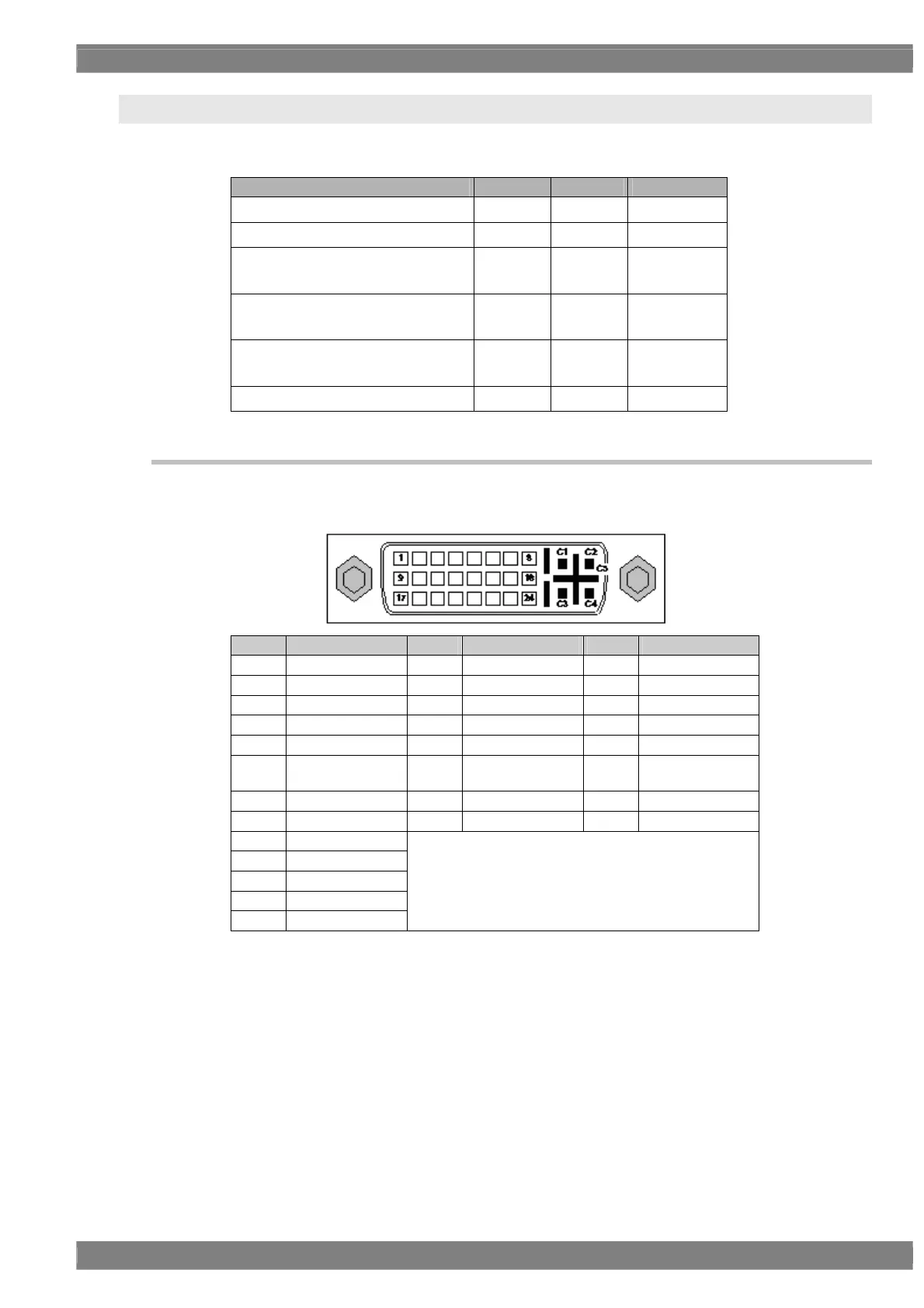
4.4.1 Connectors and pin assignments
Connector: DVI-I (74320-1004) made by Morex
Output: iTMDS, TMDS (8-bit DVI compatible mode)
Pin no. Signal Pin no. Signal Pin no. Signal
1 TMDS DATA2- 9 TMDS DATA1- 17 TMDS DATA0-
2 TMDS DATA2+ 10 TMDS DATA1+ 18 TMDS DATA0+
3 TMDS DATA2/4 G 11 TMDS DATA1/3 G 19 TMDS DATA0/5 G
4 TMDS DATA4- 12 TMDS DATA3- 20 TMDS DATA5-
5 TMDS DATA4+ 13 TMDS DATA3+ 21 TMDS DATA5+
6 DDC CLK 14
+5 V (DDC power
supply *1)
22 TMDS CLK G
7 DDC DATA 15 Ground 23 TMDS CLK+
8 Analog Vsync 16 SENSE 24 TMDS CLK-
C1 Analog Red
C2 Analog Green
C3 Analog Blue
C4 Analog Hsync
C5 Analog Ground
*1: Restrictions apply to the supply current of the DDC power supply. Refer to “12.3 Concerning the
maximum current consumption of the DDC (DP_PWR) power supply.”
 Loading...