162
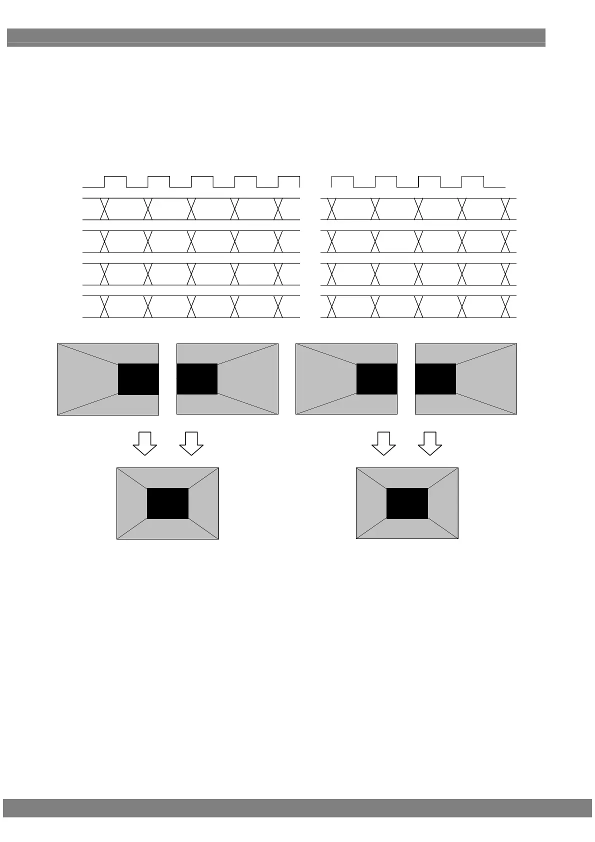
Setting (6) [Dual (16 bits)], [2 split], configuration [8 + 8 bits]
With channels 1 and 3 forming one set and channels 2 and 4 forming another set, the left half of the image is output
using one set and the right half of the image is output using the other set.
The 8 upper bits are output to channels 1 and 2, and the remaining 8 lower bits are output to channels 3 and 4.
The example is that the resolution is 1280 × 1024, the dot clock frequency is 108 MHz with 16 bits level, 8 bits are
output to channel 1 and 8 bits are output to channel 2.
D 0 D 1 D 2 D 3
・・・
・・・
D 636 D 637 D 638 D 639
CLK
54MHz
1CH
2CH
3CH
4CH
D 640 D 641 D 642 D 643
・・・
D 1276 D 1277 D 1278 D 1279
D 640 D 641 D 642 D 643
・・・
D 1276 D 1277 D 1278 D 1279
D 0 D 1 D 2 D 3
・・・
D 636 D 637 D 638 D 639
[7:0] [7:0] [7:0] [7:0] [7:0] [7:0] [7:0] [7:0]
[15:8] [15:8] [15:8] [15:8] [15:8] [15:8] [15:8] [15:8]
[15:8] [15:8] [15:8] [15:8] [15:8] [15:8] [15:8] [15:8]
[7:0] [7:0] [7:0] [7:0] [7:0] [7:0] [7:0] [7:0]
Upper Bit [15:8]
Lower Bit [7:0]
Upper Bit [15:8]
Lower Bit [7:0]
Upper Bit [15:8]
Lower Bit [7:0]
1CH 2CH 3CH 4CH
 Loading...