58
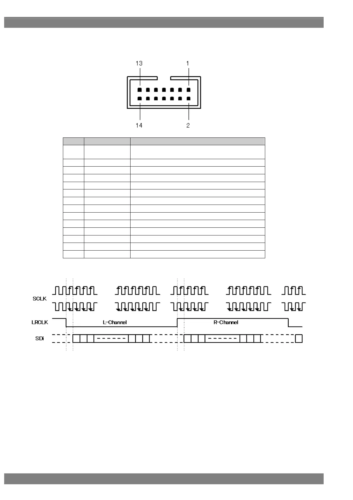
I2S (Option)
Connector: 7614-5002PL (made by 3M)
Pin no. Signal Description
1 MCLK IN
Input a clock signal with a frequency of 24.576 MHz or
22.5792 MHz.
2 GND
3 SCLK IN Input the I2S SCLK signal.
4 GND
5 LRCLK IN Input the I2S LRCLK signal.
6 GND
7 SD0 IN Input the I2S SD0 signal.
8 GND
9 SD1 IN Input the I2S SD1 signal.
10 GND
11 SD2 IN Input the I2S SD2 signal.
12 GND
13 SD3 IN Input the I2S SD3 signal.
14 GND
Input the signals at the following timing.
* For the SCLK and LRCLK signals, input signals which are synchronized with MCLK.
The leading edge of SCLK can be set using “4.2.5 Embedded audio, high bit rate audio (option).”
 Loading...