Chapter 4 INTERFACE SETTINGS
111
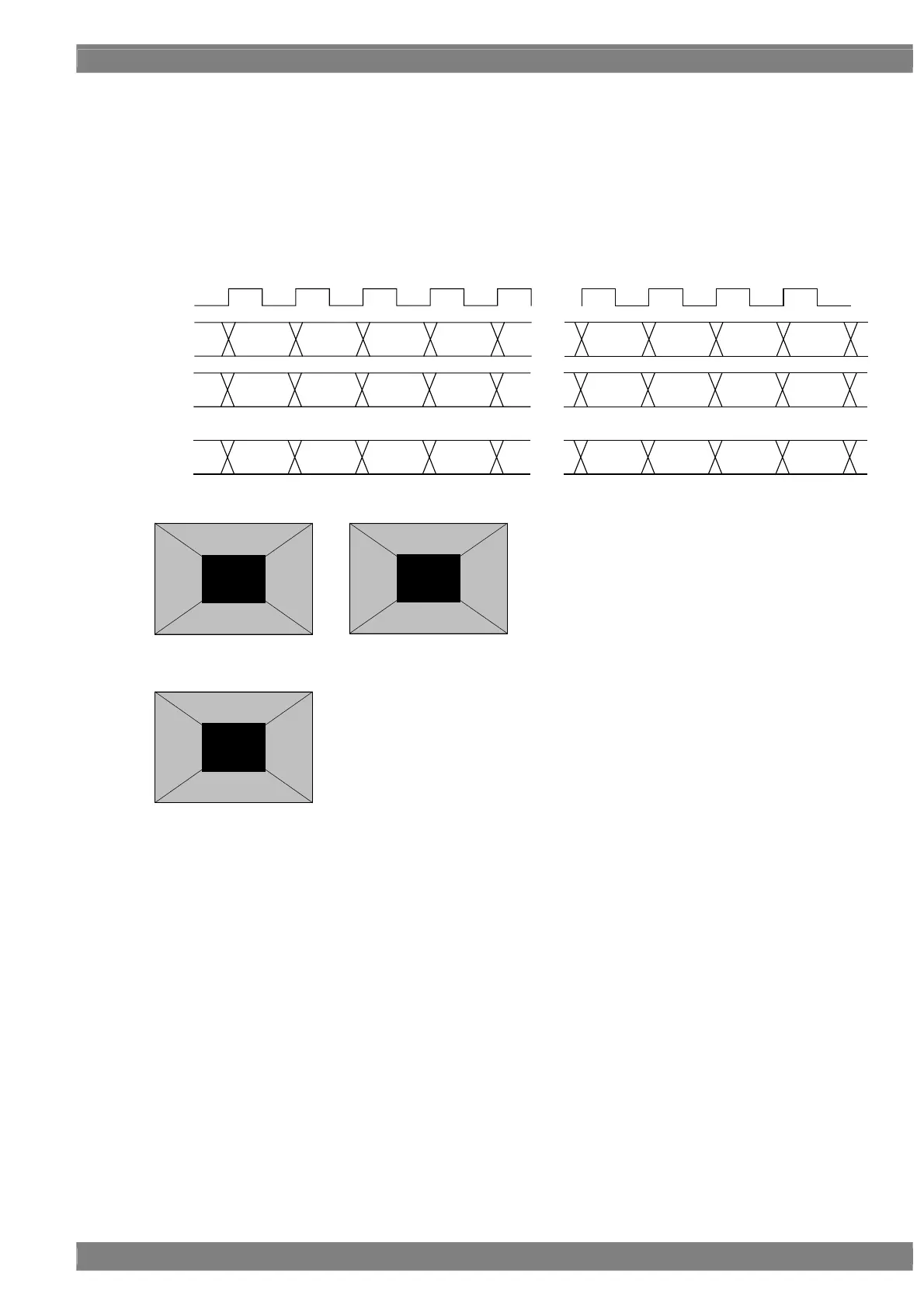
<Specifications with 16-bit output>
[Single (16bit)]
The 16-bit images are output with channel 1 master and channel 1 slave making a pair.
The higher 8 bits are output to the channel 1 master and the lower 8 bits to the channel 1 slave.
With channel 2, the higher 8 bits are output, and the lower bits are discarded.
Given here as an example for explanatory purposes is a case where the resolution is 1280 × 1024, the dot clock
frequency is 108 MHz and the 16 bits output consisting of 8 bits for channel 1 and 8 bits for channel 2.
D 0 D 1 D 2 D 3
・・・
・・・
D 1276 D 1277 D 1278 D 1279
CLK
108MHz
D 0 D 1 D 2 D 3
・・・
D 1276 D 1277 D 1278 D 1279
[15:8] [15:8] [15:8] [15:8] [15:8] [15:8] [15:8] [15:8]
[7:0] [7:0] [7:0] [7:0] [7:0] [7:0] [7:0] [7:0]
D 0 D 1 D 2 D 3
・・・
D 1276 D 1277 D 1278 D 1279
[15:8] [15:8] [15:8] [15:8] [15:8] [15:8] [15:8] [15:8]
1ch
Master
1ch
Slave
2ch
Upper Bit [15:8]
Lower Bit [7:0]
Upper Bit [15:8]
1CH Master
1CH Slave
2CH
 Loading...