Chapter 4 INTERFACE SETTINGS
139
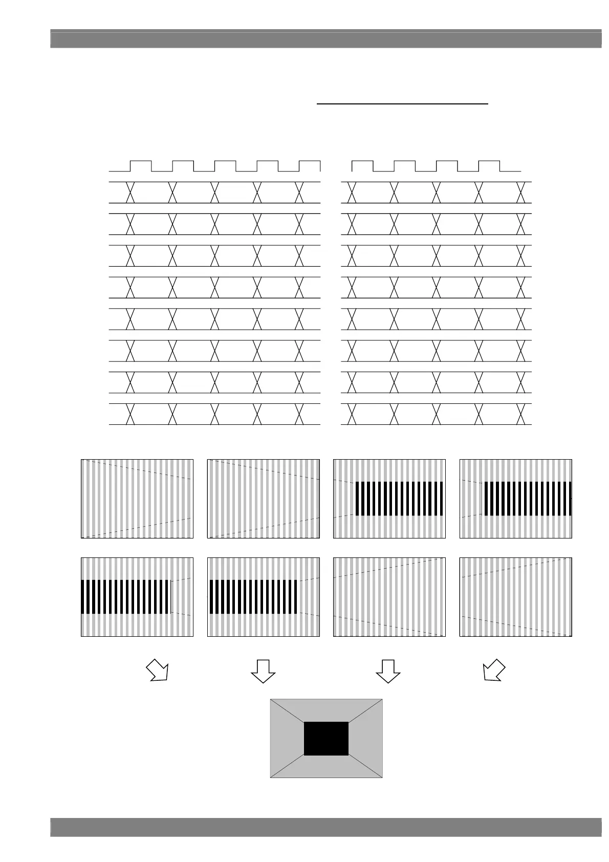
[9] MODE8 (Octal Link ) (split vertically into 2 + dividing <2>)(Dividing Cross Mode)
Channels 1 to 8 are used. The screen is split vertically into 2 and output from each board. CH1-2 outputs 1/4 of the
left side. CH3-4 outputs 1/4 of the left from the center. CH5-6 outputs 1/4 of the right from center. CH7-8 outputs
1/4 of right side with the below pixel assignment. Note) This is same as Mode 3 (Octal Link)
Given here as an example of the resolution is 4096 × 2048, the dot clock frequency is 1184 MHz with the 10 bits
output.
・・・
[9:0]
・・・
[9:0]
・・・
[9:0]
・・・
[9:0]
・・・
[9:0]
・・・
[9:0]
・・・
[9:0]
・・・
[9:0]
・・・
L0~L2159
L0~L2159
L0~L2159
L0~L2159
L0~L2159
L0~L2159
L0~L2159
L0~L2159
CLK
148MHz
1CH
2CH
3CH
4CH
5CH
6CH
7CH
8CH
D 0
D 1
D 1024
D 1025
D 2048
D 2049
D 3072
D 3073
[9:0]
[9:0]
[9:0]
[9:0]
[9:0]
[9:0]
[9:0]
[9:0]
D 2
D 3
D 1026
D 1027
D 2050
D 2051
D 3074
D 3075
[9:0]
[9:0]
[9:0]
[9:0]
[9:0]
[9:0]
[9:0]
[9:0]
D 4
D 5
D 1028
D 1039
D 2052
D 2053
D 3076
D 3077
[9:0]
[9:0]
[9:0]
[9:0]
[9:0]
[9:0]
[9:0]
[9:0]
D 6
D 7
D 1030
D 1031
D 2054
D 2055
D 3078
D 3079
[9:0]
[9:0]
[9:0]
[9:0]
[9:0]
[9:0]
[9:0]
[9:0]
D 1016
D 1017
D 2040
D 2041
D 3064
D 3065
D 4088
D 4089
[9:0]
[9:0]
[9:0]
[9:0]
[9:0]
[9:0]
[9:0]
[9:0]
D 1018
D 1019
D 2042
D 2043
D 3066
D 3067
D 4090
D 4091
[9:0]
[9:0]
[9:0]
[9:0]
[9:0]
[9:0]
[9:0]
[9:0]
D 1020
D 1021
D 2044
D 2045
D 3068
D 3069
D 4092
D 4093
[9:0]
[9:0]
[9:0]
[9:0]
[9:0]
[9:0]
[9:0]
[9:0]
D 1022
D 1023
D 2046
D 2047
D 3070
D 3071
D 4094
D 4095
5CH 6CH 7CH 8CH
1CH 2CH 3CH 4CH
 Loading...