Installation 107/188
3 842 564 874/2021-04, MIT: ActiveMover, Bosch Rexroth AG
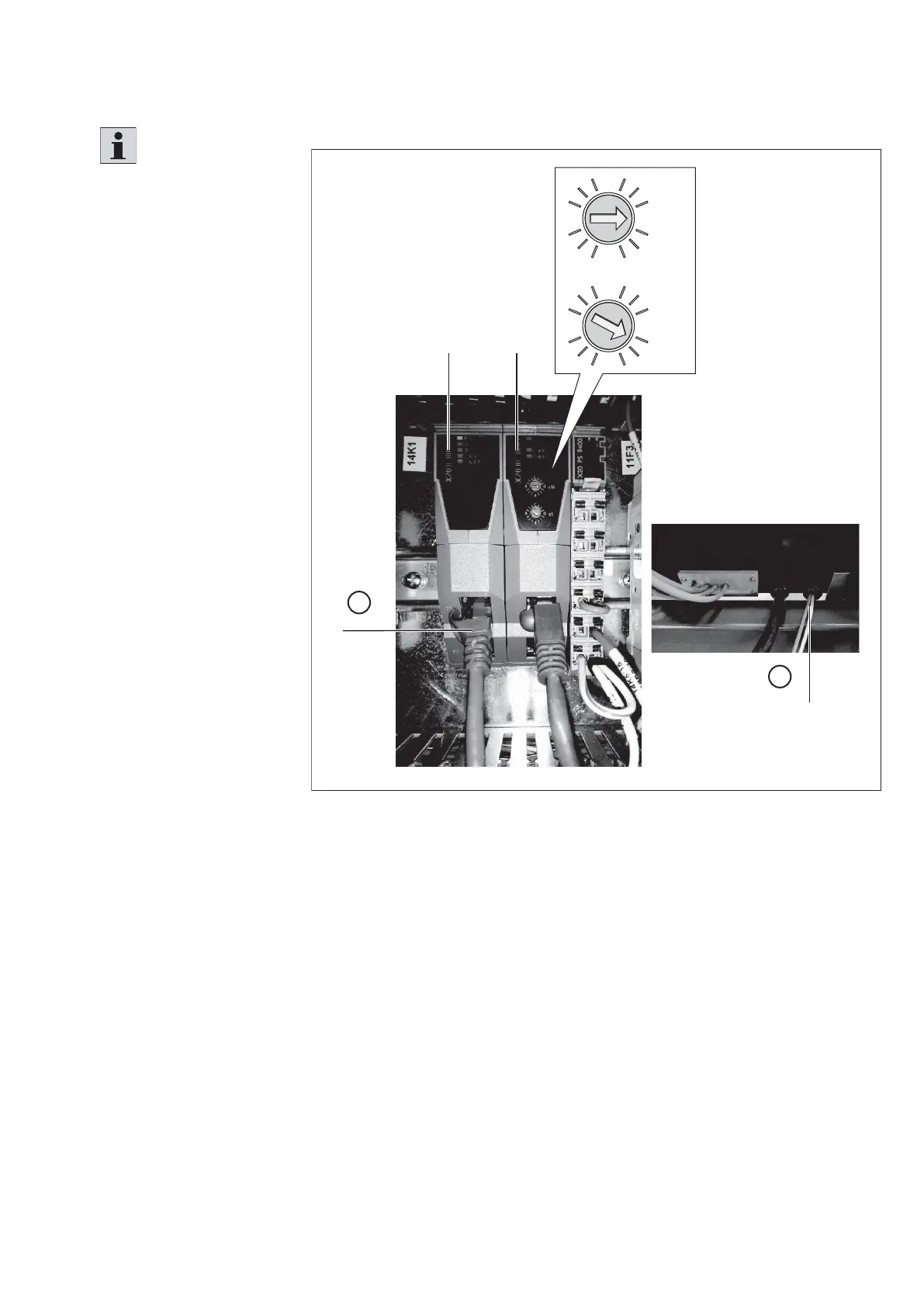
7.6.17 PLC
Fig. 80:
A
D
1
2
X
B C
557 186-74
0x 1B
C
4
0 x 16B
C
4
PLC connection
A:
PLC terminal
B:
PLC interface module (options: Ethernet/IP™, PROFINET®, EtherCAT®, etc.
(depending on customer order)
Notice: For the PLC interface extension, up to 2 interface modules can be
optionally inserted for the Ethernet/ IP™ and EtherCAT® bus protocols in the
bus controller.
C:
Ethernet POWERLINK module
D:
Cable entry point
Please note:
• The bus protocol of the
interface module depends
on the customer order
(e.g. EtherNET/IP™,
PROFINET® EtherCAT® ,
etc.).
• The connection cable for
the PLC connection (A) is
not included in the scope
of delivery.
• The setting of the
participant address of
the Ethernet POWERLINK
module from the bus
controller (standard
setting of the rotary
switches 1 x 1 and
0 x 16, see detail X)
must be checked and
set, if necessary, before
commissioning the control
cabinet.
• If the setting of the rotary
switches is to be changed,
proceed as follows:
– Switch off main switch
on the control cabinet.
– Change the setting of
the rotary switches.
– Switch on the main
switch.
1. Guide the connection
cable through the cable
gland on the rear of the
control cabinet (C).
2. Connect the PLC
according to the circuit
diagram.
3. Set the rotary switches
according to the graphic.