86/188 Installation
Bosch Rexroth AG, MIT: ActiveMover, 3 842 564 874/2021-04
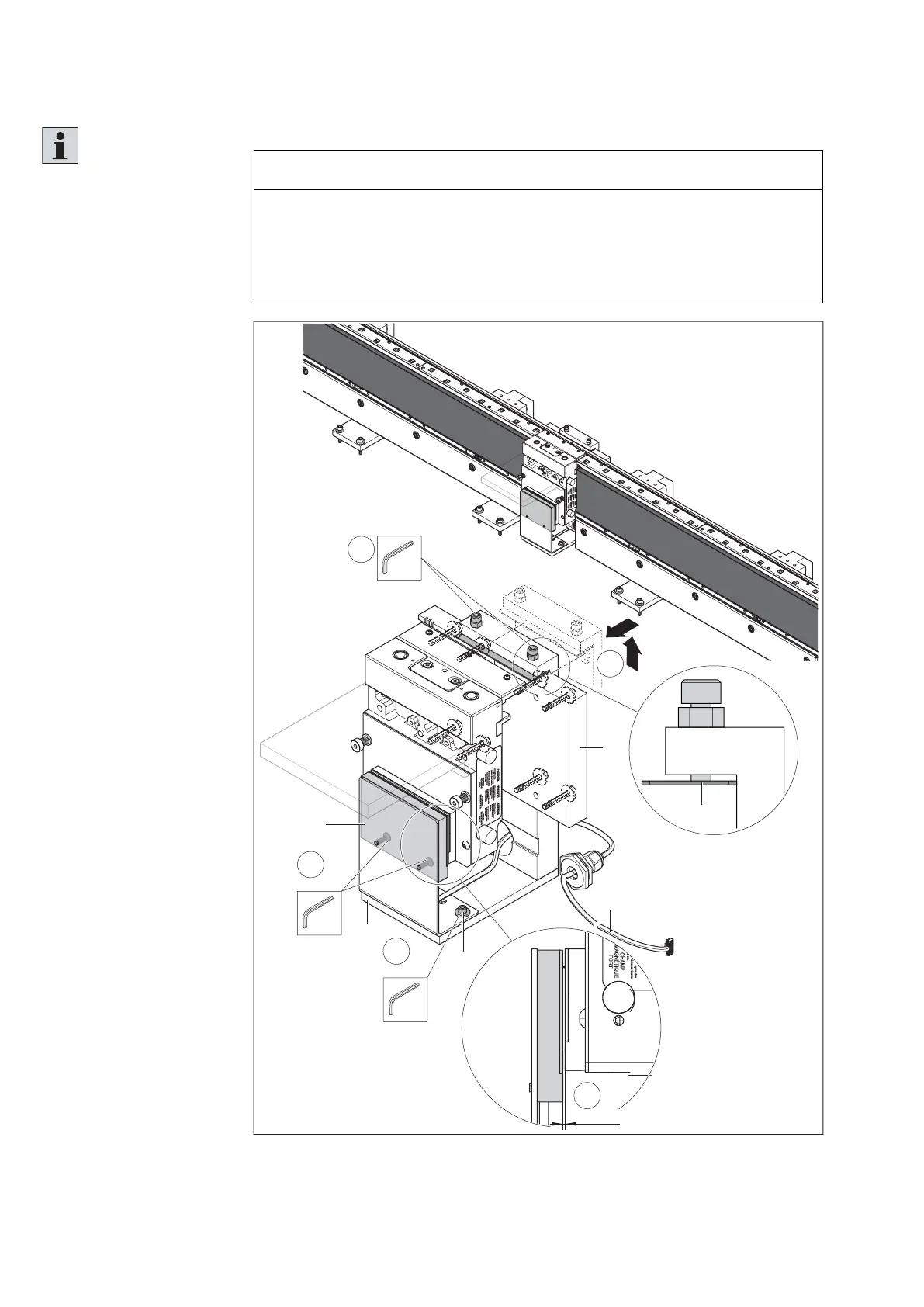
7.5.15 Assembling, adjusting and connecting the IR reading head ID system
NOTICE
The IR probe connection cable can only be introduced into the electronic box if
no power supply is connected to the section module. Then the cable entry point
in the rear wall is already occupied.
If necessary, check another possible installation location of the IR reading head
or power supply.
Fig. 62:
1
5
5
4
1,0 mm
SW3
2x
SW4
2x
M
D
=5 Nm
E
C
B
A
D
SW5
2x
3
M
D
=7 Nm
F
557 186-56
Assembling and adjusting the IR reading head
Please note:
• The mounting kit for the IR
reading head is mounted
at the joint between 2
section modules on the
profi le connector (D).
• Make sure that the
clamping plate (F) is
located between the
clamping screws and the
profi le connector.
1. Mount the IR reading
head (A) on the
mounting kit (B).
2. Guide the connection
cable (C) of the IR
reading head through the
bore in the mounting kit.
3. Slide the long leg of the
mounting kit under the
section modules and
place the mounting kit on
the fi xing screws of the
profi le connector (D).
4. Tighten the clamping
screws and counter
them.
5. Set the distance
between the IR data
carrier and the reading
head as closely as
possible to 1.0 mm.
To do this, loosen the
fi xing screws (E) and
move the holder of the
IR reading head.