140/188 Maintenance and repair
Bosch Rexroth AG, MIT: ActiveMover, 3 842 564 874/2021-04
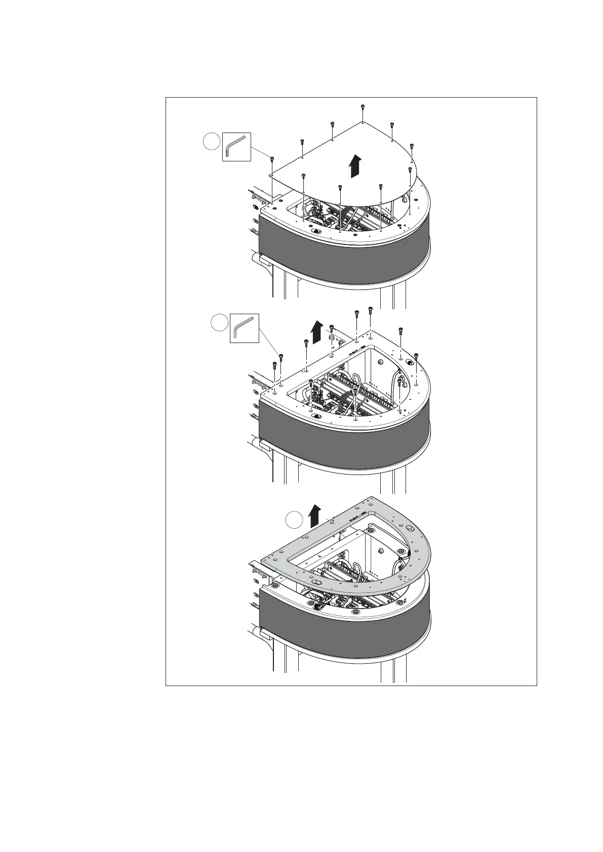
10.4.12 Replacing the upper V-rail (curve module)
Fig. 98:
557 186-87
3
SW4
10x
4
SW5
11x
5
M
D
=16 Nm
M
D
=10 Nm
Replacing the upper V-rail (curve module)
Necessary spare parts
• Upper V-rail, curve module
1. Remove the upper V-rails
of the two adjacent
section modules
(see chapter 10.4.11).
2. Remove the left
and right measuring
system sensor units
(see chapter 10.4.24).
3. Remove the protective
cover of the curve
module.
4. Remove the fi xing screws
(11 items) from the
upper V-rail.
5. Pull the upper V-rail up
and off.
6. Clean the top side of
the curve module with
a soft cloth.
7. Install the new upper
V-rail in reverse order.
8. If necessary, align
the upper V-rail
(see chapter 7.5.11).
9. Calibrate the measuring
system sensor units
(see chapter 10.5).