Installation 97/188
3 842 564 874/2021-04, MIT: ActiveMover, Bosch Rexroth AG
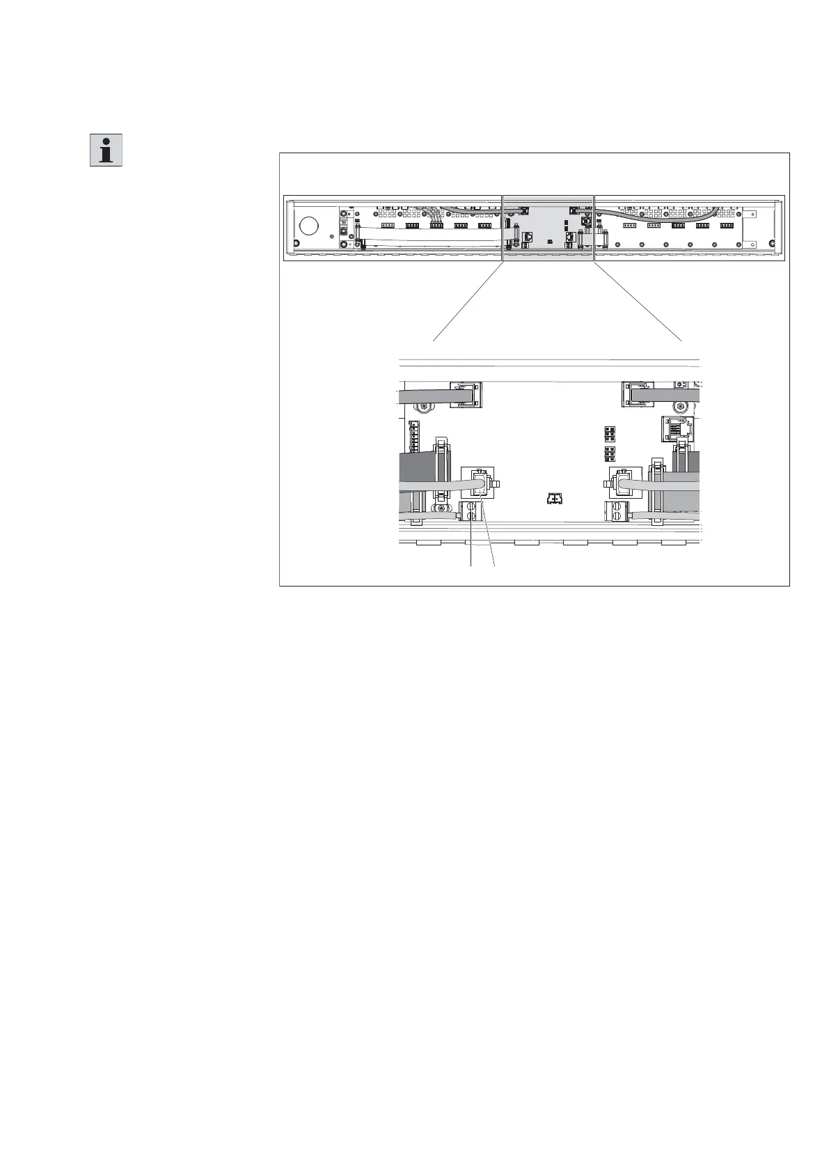
7.6.7 Connecting network and cable control voltage (24 V)
(from right section/curve module)
Fig. 71:
EF
557 186-65
Connecting network cables (from right section/curve module)
7.6.8 Connecting the network connections and power supplies in the
control panel
Please refer to the corresponding information from the circuit diagram.
Please note:
• The connection of an
adjacent curve module is
the same as connecting an
adjacent section module.
• For further information on
the electrical connection,
please refer to the circuit
diagram included in the
scope of delivery.
• The electronics voltage
supply cable (24 V) can
be connected to either
of the two contacts on
terminal G.
1. Connect the network
cable to terminal F on
the printed circuit board
(gateway).
2. Connect the control
voltage cable (24 V)
to terminal E.
Notice:
For connecting the network
cables, please observe the
additional information in
chapter 7.6.10.