Maintenance and repair 139/188
3 842 564 874/2021-04, MIT: ActiveMover, Bosch Rexroth AG
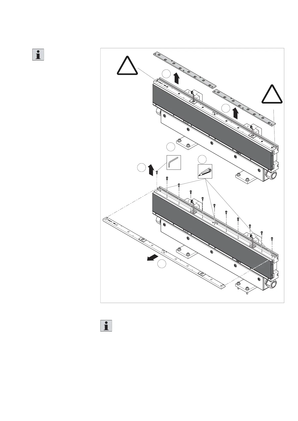
10.4.11 Replacing the upper V-rail (section module)
Fig. 97:
2
SW5
11x
4
M
D
=16 Nm
!
X = 0,5 mm
!
X = 0,5 mm
1
1
3
2
557 186-86
Replacing the upper V-rail (section module)
Please note:
The removed compensating
intermediate layers must be
installed exactly at the same
position when installing the
new upper V-rail.
Necessary spare parts
• Upper V-rail,
section module
3 842 555 965
1. Remove the left
and right measuring
system sensor units
(see chapter 10.4.23).
2. Remove the fi xing screws
(11 items) from the
upper V-rail.
3. Only remove the upper
V-rail in the forward
direction.
4. Mark the position of
the compensating
intermediate layers and
store them safely.
5. Clean the top of the
section module using a
soft cloth.
6. Install the new upper
V-rail in reverse order.
7. If necessary, align
the upper V-rail
(see chapter 7.5.11).
8. Calibrate the measuring
system sensor units
(see chapter 10.5).
Please note:
• The V-grooves on both sides of the upper V-rail prevent lifting of the rail.
• The gap at both ends of the upper V-rail should be about 0.5 mm on both sides.