Maintenance and repair 161/188
3 842 564 874/2021-04, MIT: ActiveMover, Bosch Rexroth AG
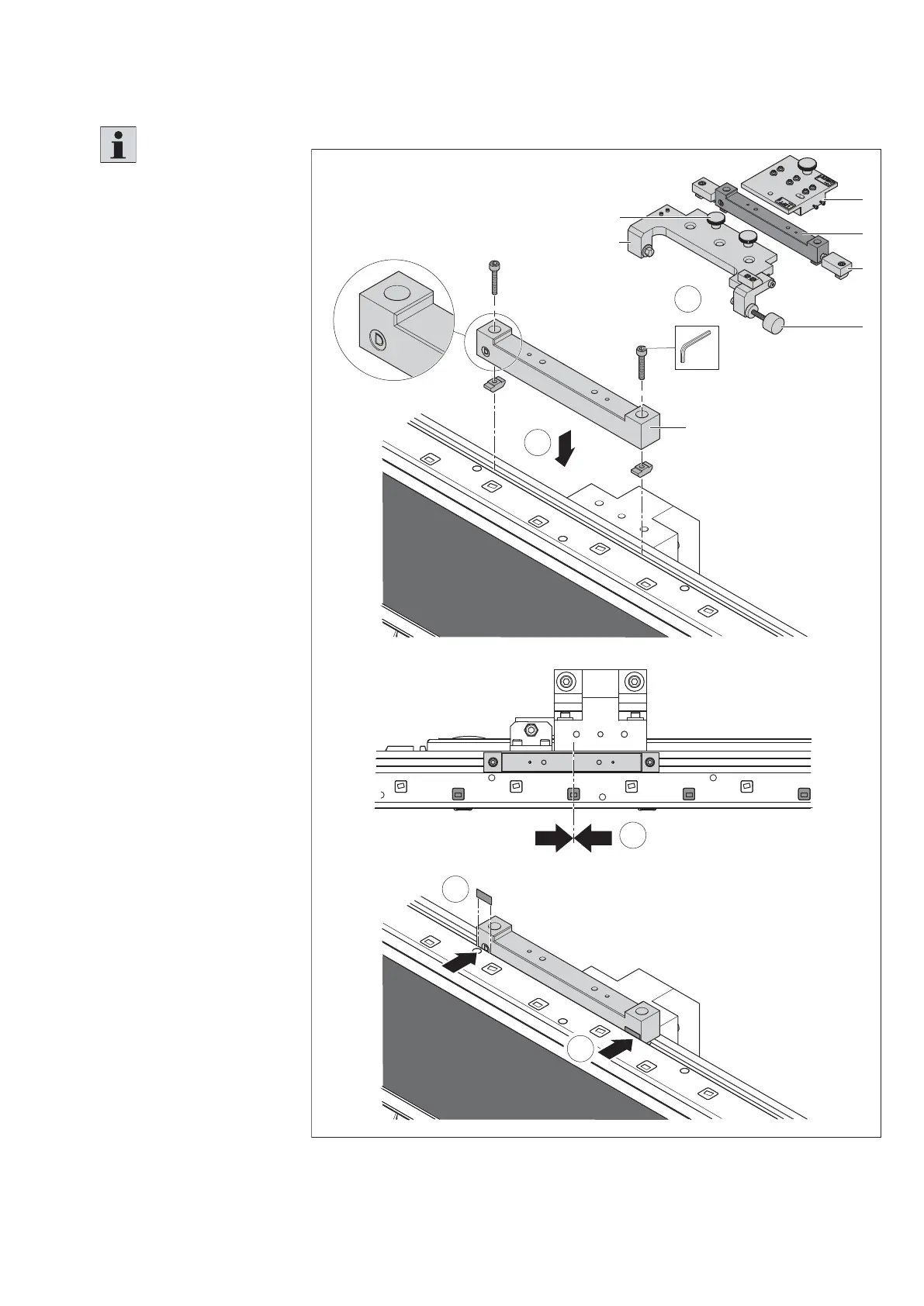
10.5.4 Assembling and aligning the calibration set (optional)
Fig. 119:
SW4
2x
1
1
B
B
A
C
E
D
F
3
3
2
557 186-108
Assembling the measuring system adjusting tool (1)
Please note:
• The calibration set is
required for adjusting/
calibrating the measuring
system on the WT.
• Incorrect use of the
calibration set can
damage the WT and
ActiveMover.
• Avoid assembly at
a transition to the next
section module.
• Before commissioning,
the calibration set must
be removed.
A:
Position indicator
B:
Fixing element
C:
Alignment block
D:
Knurled screw
E:
Reference system
F:
Knurled screw
1. Place the fi xing
element (B) on a section
module in the slot
behind the sensor unit.
The side marked with D
must point forward to
the sensor unit.
2. Align the fi xing element
centrally to an encoder
with an uneven number
(see also chapter 10.5.3).
3. To push the fi xture
backwards and align
it parallel to the upper
V-rail, insert appropriate
intermediate layers
between the fi xing
element and the sensor
unit.