56/188 Installation
Bosch Rexroth AG, MIT: ActiveMover, 3 842 564 874/2021-04
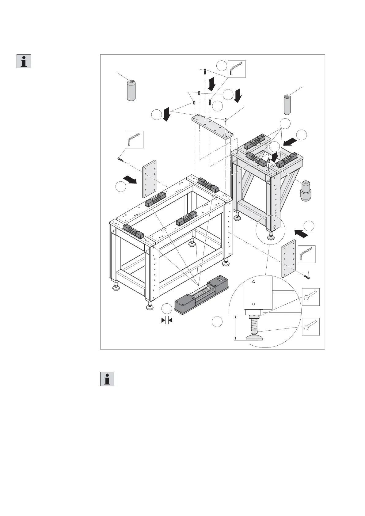
Fig. 32:
B
557 186-31
A
B
90
(45,5 ... 163,5)
SW36
SW24
4
8
8
6
2
7
SW8
8x
M
D
=80 Nm
1 x
ISO8375 –
12 x 40 – A – ST
1 x
ISO8375 –
16 x 40 – A – ST
32 x
M10 x 40
1
SW8
12x
M
D
=80 Nm
SW8
12x
M
D
=80 Nm
!
!
3
9
= 0,02 mm/m
9
16/12 mm
5
Positioning and aligning the base frame 3 842 559 451 (assembly on the right side)
Please note:
The base frame 3 842 559 451 (short, only for curve module) must be mounted on
a base frame 3 842 559 450 on the right or left. The installation is mirrored in each
case (see fi g. 32).
Please note:
The base frame
3 842 559 451 (short,
only for curve module)
must be assembled,
using connection kit
3 842 559 453, to an
already aligned base
frame 3 842 559 450
(reference system section)
and aligned accordingly.
1. Place the upper
connection plate on the
base frame and fi x it
with 2 straight pins.
2. Tighten the upper
connection plate.
3. Insert the cylinder
pin 16/12 mm into the
short base frame.
4. Position the short
base frame under the
assembled connection
plate.
5. Align the short base
frame in height and
laterally accordingly.
6. Add a straight pin for
fi xing to the upper
connection plate.
7. Tighten the upper
connection plate.
8. Mount the side
connection plates
(on both sides).
9. Check the alignment
of both base frames
longitudinally and
transversely
using a
machine water level.