Installation 65/188
3 842 564 874/2021-04, MIT: ActiveMover, Bosch Rexroth AG
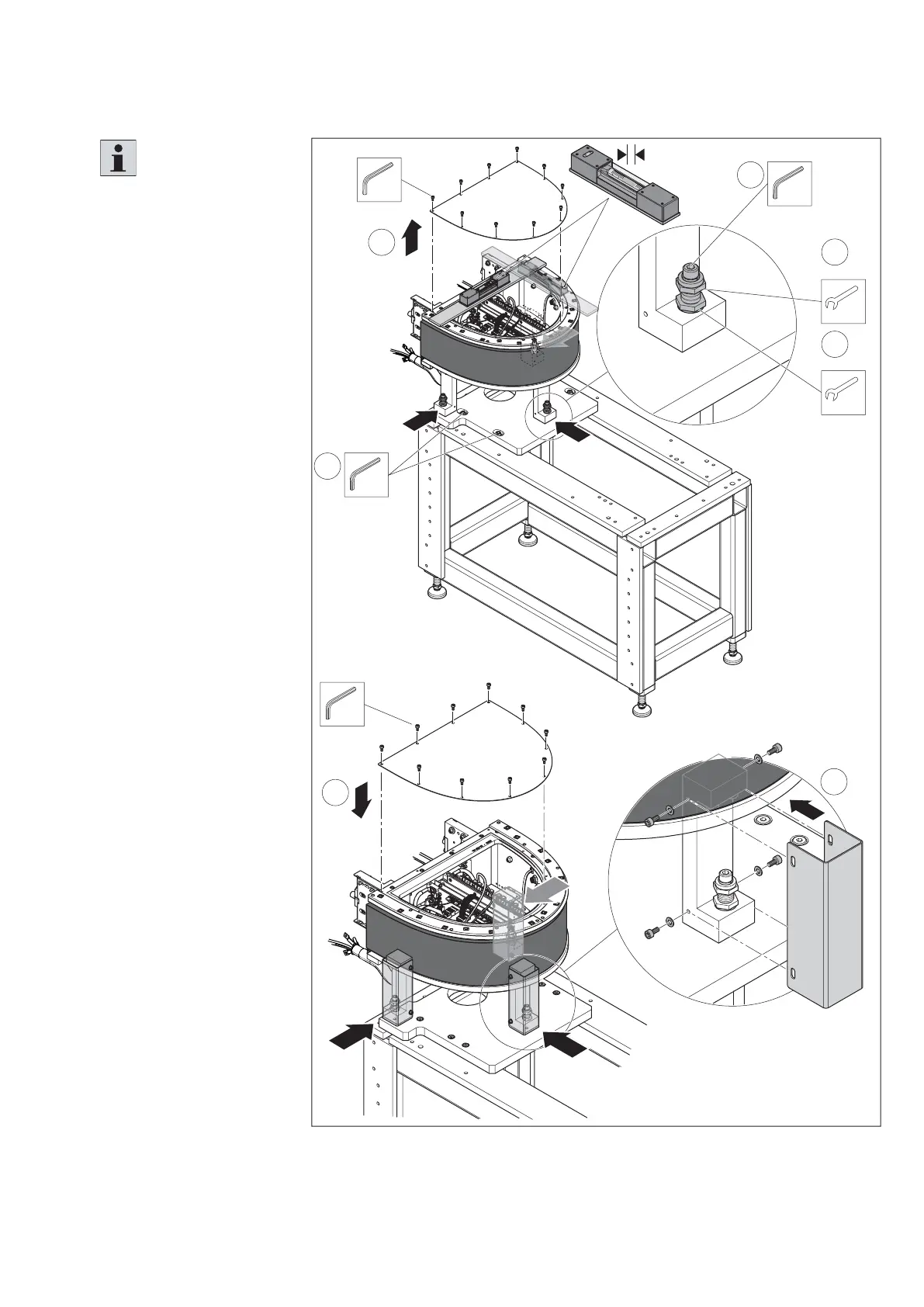
Fig. 41:
4
7
5
6
557 186-40
10
SW4
10x
SW13
3x
SW13
3x
SW6
3x
M
D
=40 Nm
9
SW8
4x
M
D
=80 Nm
11
SW4
10x
M
D
=10 Nm
= 0,02 mm/m
Assembling the curve module on a base frame (2)
Please note:
It may be necessary to
realign the curve module in
height and position during
assembly of the overall
system.
4.
For a more detailed
alignment, disassemble
the cover of the curve
module.
5. Align the curve
module longitudinally
and crosswise using
a machine water level
with the setting screws.
6. Counter the setting
screws with the lock
nuts.
7. Tighten the fi xing
screws.
8. Align the curve module
centered and face to the
base frame
9. Tighten the screws of
the fi xing plate.
10. Install the covers on the
module holders.
11. Install the cover of the
curve module.