72/188 Installation
Bosch Rexroth AG, MIT: ActiveMover, 3 842 564 874/2021-04
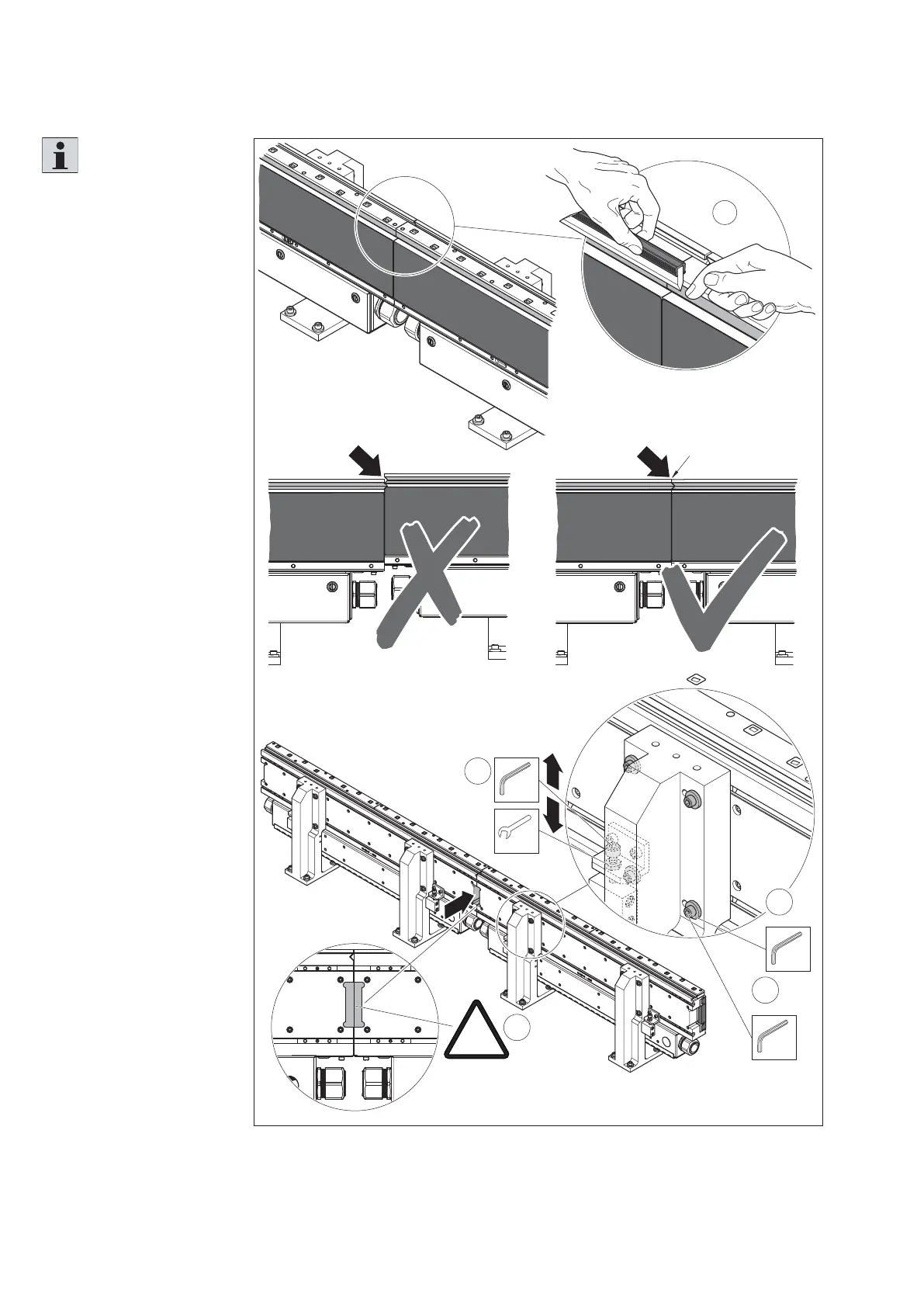
Fig. 48:
2
SW5
4x
5
SW5
4x
M
D
=16 Nm
3
SW13
SW6
557 186-46
1
!
X = 0,5 mm
M
D
=21 Nm
4
∆
max
≤ 70 µm
!
Setting the height offset of the section modules (rough setting)
Please note:
• The height offset ∆ must
not exceed 70 µm. You
can see an example for
measuring the height
offset in fi g. 49.
Fine adjustment will be
carried out at a later point
in time.
• Due to thermal expansion
during operation, the
modules must always have
a distance of X = 0.5 mm.
Required tools
• Plastic feeler gage 0.5 mm
1. Use the fi nger and a
straightedge to ensure
that the upper V-rails
at the joints have as
little height offset as
possible.
2. To align the section
modules, loosen the
upper fi xing screws of
both module holders.
3. Adjust the height using
the setting screw.
4. Make sure that all
modules have a distance
of X = 0.5 mm.
5. Tighten the fi xing
screws.