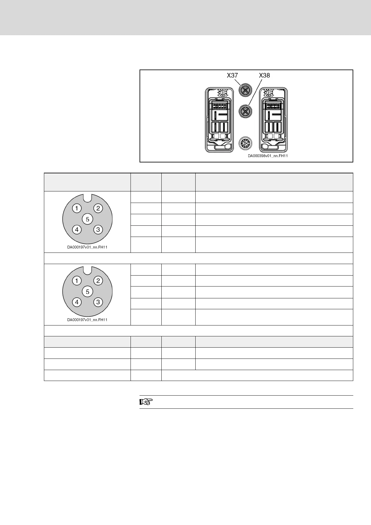
6.3.2 X37, X38, digital inputs/outputs
Fig. 6-3: X37 and X38
View Connectio
n
Signal
name
Function
X37.1
U
ext
External supply 19 … 30 V, max. 1 A, connected to X38.1
X37.2 I/O_3 dig. I/O, configurable
X37.3
0 V
ext
Reference potential; external supply, connected to X38.3
X37.4 I/O_1 dig. I/O, configurable, can be used as probe
X37.5 PE For cable shield
X38.1
U
ext
External supply 19 … 30 V, max. 1 A, connected to X37.1
X38.2 I/O_4 dig. I/O, configurable
X38.3
0 V
ext
Reference potential; external supply, connected to X37.3
X38.4 I/O_2 dig. I/O, configurable, can be used as probe
X38.5 PE For cable shield
M12 (5‑pin, A‑coded) female Unit min. max.
Connection cable, stranded wire
mm
2
0.25 0.25
Cable cross section AWG - -
Ready-made connection cable RKS0010 (optional accessory)
Tab. 6-18: Function, pin assignment, properties
The digital inputs/outputs comply with IEC 61131-2, type 1.
Properties
● There is a total of 4 configurable, isolated inputs/outputs which are
distributed over two 5-pin M12 connectors (X37 and X38).
The configuration is carried out with the parameter "P-0-0300, Digital
I/Os, assignment list".
● The inputs I_1 (X37.4) and I_2 (X38.4) can be used as probe inputs.
IndraDrive Mi Drive Systems with KCU02, KSM02,
KMS02/03, KMV03, KNK03, KLC03
159/407
Connection points
R911335703_Edition 04 Bosch Rexroth AG
 Loading...


