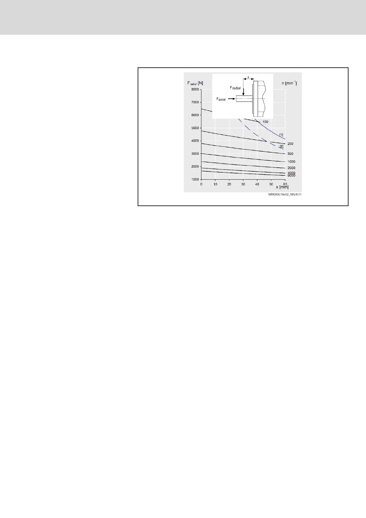
Radial load, axial load
[1] Breakage characteristic of the plain shaft
[2] Breakage characteristic of the shaft with keyway
n Arithmetic mean speed
x Point of application of force
Fig. 7-26: Exemplary shaft load diagram
Maximum allowed radial force F
ra‐
dial_max
The maximum allowed radial force F
radial_max
depends on the following factors:
● Shaft break load
● Point of application of force x
● Shaft design (plain [1]; with keyway [2])
Allowed radial force F
radial
The allowed radial force F
radial
depends on the following factors:
● Arithmetic mean speed (n
mean
)
● Point of application of force x
● Bearing service life
Allowed axial force F
axial
The maximum allowed axial force F
axial
is specified in the technical data.
Average speed
The run-up and braking times can be ignored in the calculation, if the time in
which the drive is operated at a constant speed is significantly greater than
the acceleration and braking time. In the exact calculation of the average
speed according to the following example, the run-up and braking times are
taken into account.
IndraDrive Mi Drive Systems with KCU02, KSM02,
KMS02/03, KMV03, KNK03, KLC03
251/407
Notes on project planning
R911335703_Edition 04 Bosch Rexroth AG
 Loading...