14 Appendix
14.1 Digital inputs
14.1.1 Digital inputs type A (standard)
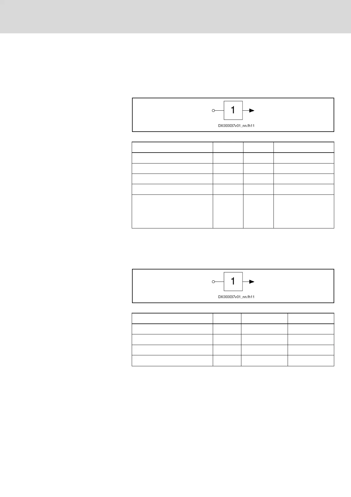
Fig. 14-1: Symbol
Data Unit Min. Max.
Allowed input voltage V -3 30
High V 15 30
Low V -3 5
Current consumption mA 2 5
Control delay µs 1000 + position
controller clock
200 + position controller
clock
1)
1) Applies to optional I/O extension DA
Tab. 14-1: Digital inputs type A
14.1.2 Digital inputs (safety technology L options)
The digital inputs correspond to IEC 61131, type 2.
Fig. 14-2: Symbol
Data Unit Min. Max.
Allowed input voltage V -3 30
High V 11 30
Low V -3 5
Current consumption
1)
mA 7 15
1) For KCU02, the specified values must be multiplied with the
number of zone nodes of the drive line.
Tab. 14-2: Digital inputs (safety technology L options)
IndraDrive Mi Drive Systems with KCU02, KSM02,
KMS02/03, KMV03, KNK03, KLC03
369/407
Appendix
R911335703_Edition 04 Bosch Rexroth AG

 Loading...


