7.2 Notes on electrical project planning
7.2.1 Address Selector Switch
High electrical voltage! Danger to life by
electric shock!
Before viewing the address, switch off power supply and wait until the 30-
minute discharge time has elapsed. Pull off the connectors form X103.1 and
X103.2 only thereafter.
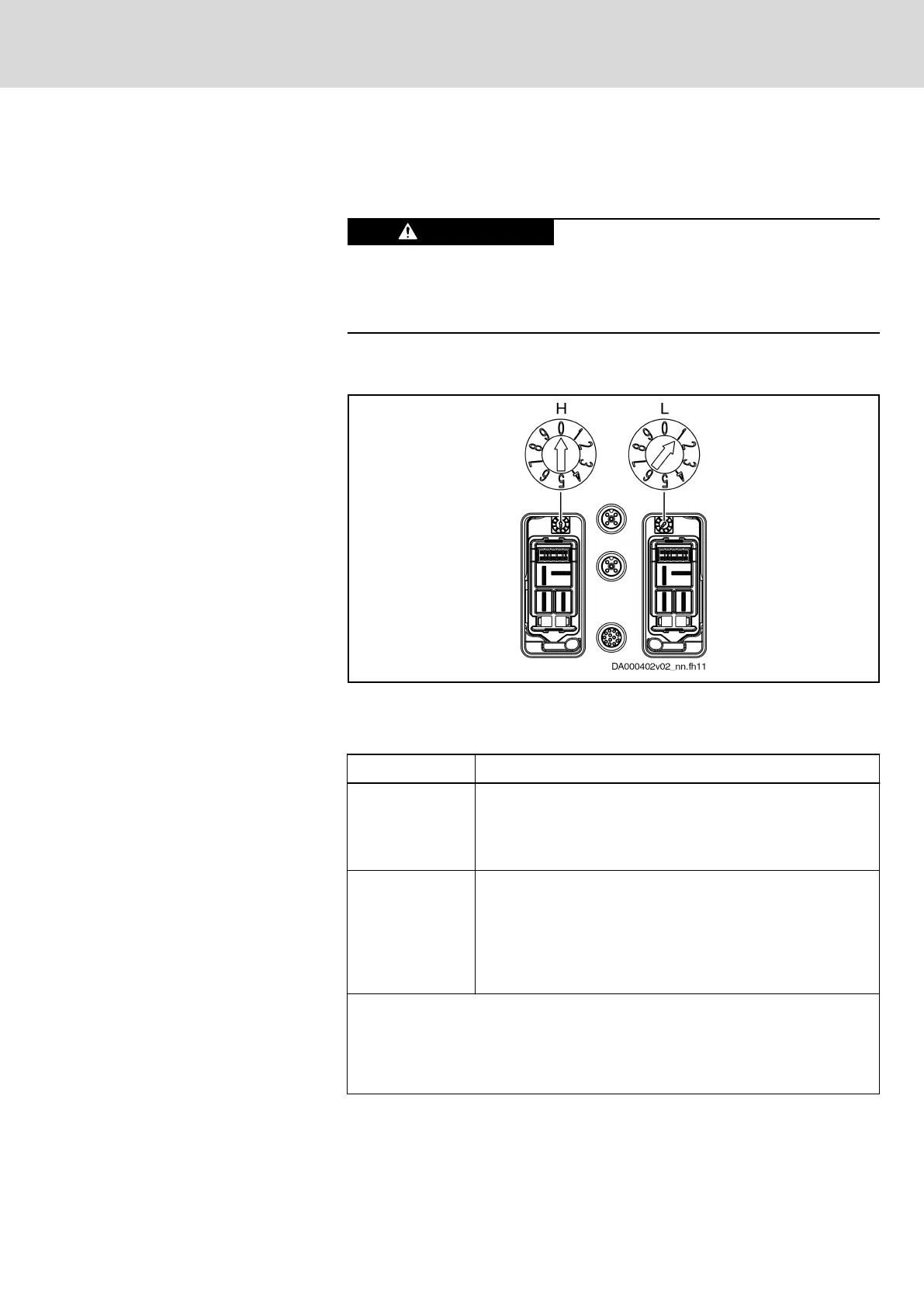
Set the address for each KSM/KMS with the H and L rotary switches. The
rotary switches are hidden under the X103.1 and X103.2 connector hoods.
H Address selector switch (×10)
L Address selector switch (×1)
Fig. 7-22: Address Selector Switch
Setting Description
"00"
H = 0
L = 0
"00" is the factory setting of the address selector switches.
This setting is not applied. The individual drive address must be
set in parameter "S‑0‑1040, Drive address of master
communication".
"01" … "99"
H = 0 … 9
L = 0 … 9
Drive address =
H×10 + L
Settings of the address selector switches are applied to
"S‑0‑1040, Drive address of master communication" during the
booting process.
Example for setting drive address "14":
H = 1, L = 4 ⇒ drive address = 1×10 + 4 = 14
See also documentation Parameter Description:
● "S‑0‑1040, Drive address of master communication"
● "S‑0‑1046, List of slave addresses in device"
● "P‑0‑4089.0.3, Device Address"
Tab. 7-9: Setting the Drive Address at H and L
IndraDrive Mi Drive Systems with KCU02, KSM02,
KMS02/03, KMV03, KNK03, KLC03
245/407
Notes on project planning
R911335703_Edition 04 Bosch Rexroth AG
 Loading...


