Data: Inputs
Data Unit min. typ. max.
Allowed input voltage V -3 30
On V 15
Off V 5
Input current mA 2 15
Input resistance kΩ 6.3
Sampling frequency kHz Depending on firmware
Delay time μs 20 100 + 1
cycle time
of position
control
Pulse width t
pulse
(probe) μs 4
Measuring accuracy t
x
(probe) μs 1
Tab. 6-19: Digital inputs
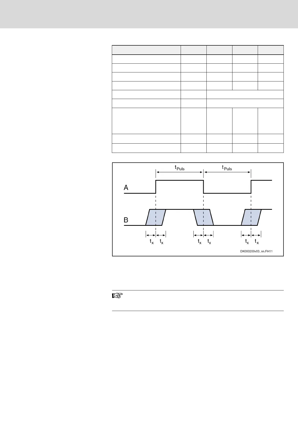
Probe input
A Signal
B Signal detection at probe input
t
Puls
Pulse width
t
x
Measuring accuracy of the signal edges
Fig. 6-5: Signal detection at probe input
Probe inputs are inputs used to acquire fast digital input signals.
For control use bounce-free switching elements (e.g., electronic
switches) to avoid incorrect evaluation.
External power supply
At the pins 1 and 3 of the connectors X37 and X38, you can connect an
external 24 V power supply to increase the maximum output current of the
digital outputs. The external 24 V supply has to comply with a voltage
tolerance of ±20%.
IndraDrive Mi Drive Systems with KCU02, KSM02,
KMS02/03, KMV03, KNK03, KLC03
161/407
Connection points
R911335703_Edition 04 Bosch Rexroth AG
 Loading...