int Internal signal processing
LK_B Internal circuit board for transmitting the communication signals
X_serc Internal communication interface
Fig. 6-11: Devices without communication output coupling
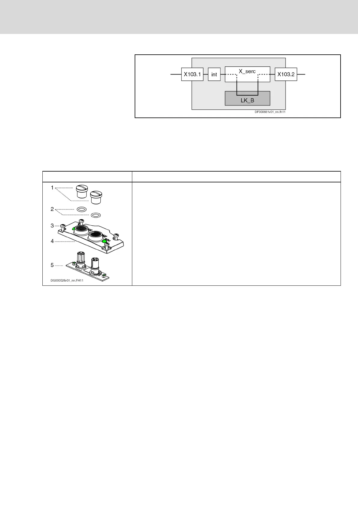
Parts
Parts Description
To replace the programming module (see X107), the cover with the connection points
X108 and X109 has to be removed.
At the bottom of the cover (4) there is a circuit board (5). Always leave the circuit
board (5) at its place. Otherwise, the seals (2) might fall out of the cover (4).
The figure shows how the parts are correctly arranged, in case you have to
reassemble the parts.
1. Protective caps (2×)
2. Seals (O-rings; 2×)
3. Screws (4×; the screws are locked and cannot fall out of the cover)
4. Cover
5. Circuit board
Tab. 6-25: Parts
IndraDrive Mi Drive Systems with KCU02, KSM02,
KMS02/03, KMV03, KNK03, KLC03
169/407
Connection points
R911335703_Edition 04 Bosch Rexroth AG
 Loading...


