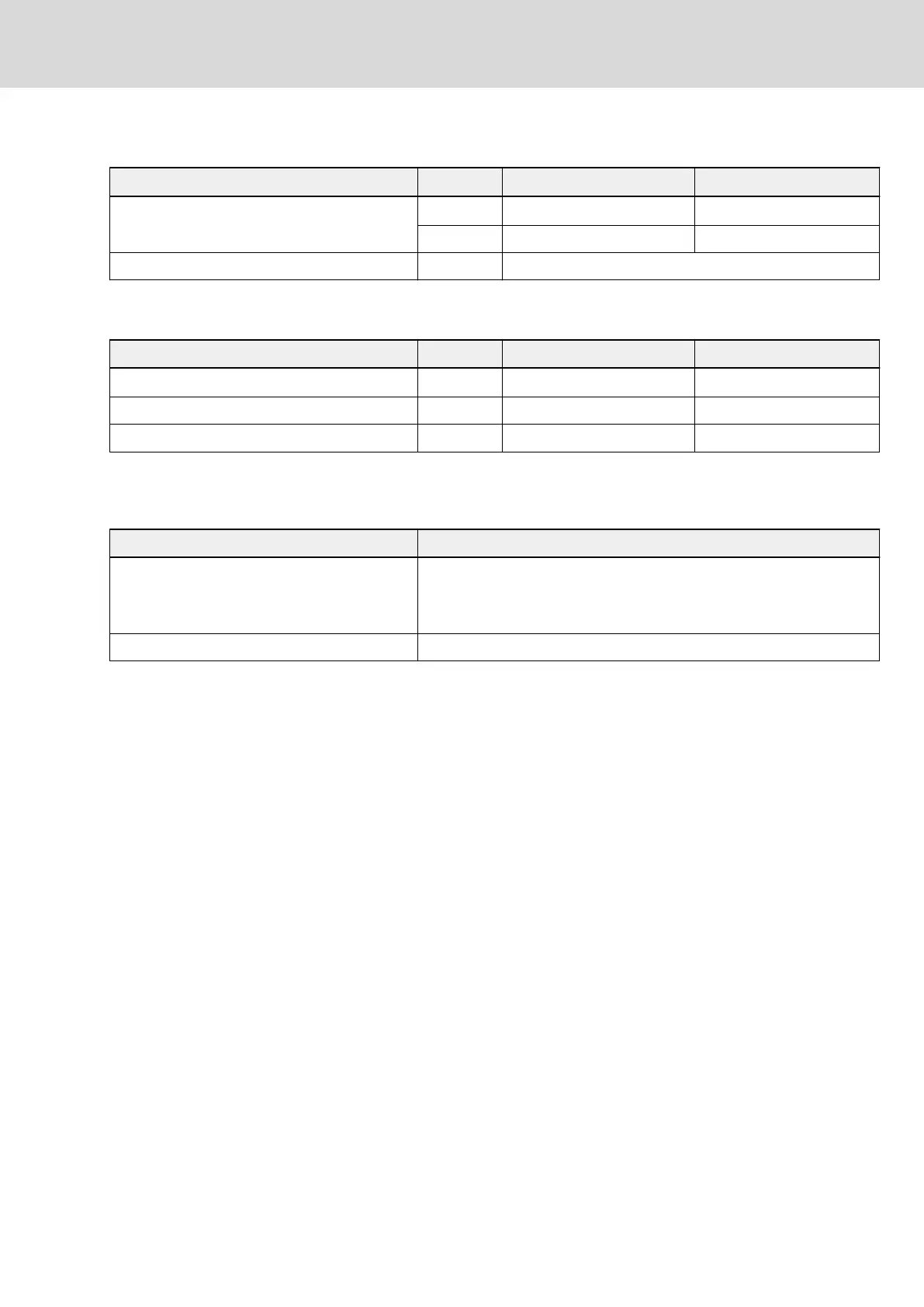
Mechanical data
Spring terminal (connector) Unit min. max.
Connection cable
Stranded wire
mm
2
0.25 1.5
AWG 24 16
Stripped length mm 10
Tab. 6-43: Mechanical data
Electrical data (output for controlling motor holding brake [XG3.3/4])
Spring terminal (connector) Unit min. max.
Output current A
0.15
1)
1.29
Overvoltage protection continuous power W n.s. 1.5
Energy absorption Ws n.s. 3
1) With deactivated brake current monitoring: 0 A
Tab. 6-44: Electrical data (output for controlling motor holding brake [XG3.3/4])
Cables
Description Value
Order type
See description of connectors:
RLS0725
RHS0725
Maximum allowed length 7.5 m
Tab. 6-45: Cables
Motor holding brake: Selection
Maximum current carrying capacity of XG3 outputs: 1.29 A
⇒ R
br (min)
= U
br (max)
/ 1.29 A
R
br (min)
: minimum allowed resistance of motor holding brake
U
br (max)
: maximum supply voltage of motor holding brake
If U
br (max)
= 24 V +5% = 25.2 V, then:
R
br (min)
= 19.53 Ω (applies to all operating and ambient conditions)
Motor holding brake: Notes on in‐
stallation
Make sure the power supply is sufficient for the motor holding brake at the
motor. Observe that voltage drops on the supply line. Use connection lines
with the largest possible cross section of single strands.
Use an external contact element in accordance with the required safety
category if you wish to supply motor holding brakes with higher currents than
the current load allowed at XG3. Make sure to comply with the required
minimum current consumption of 100 mA when using an external contact
element. Otherwise, the brake current monitor will signal an error.
IndraDrive Mi Drive Systems with KCU02, KSM02,
KMS02/03, KMV03, KNK03, KLC03
193/407
Connection points
R911335703_Edition 04 Bosch Rexroth AG
 Loading...


