CPU Circuit Board
6-6 72A-1589 Rev. C 02/01
D
DD
D
R
RR
R
A
AA
A
F
FF
F
T
TT
T
3
33
3
/
//
/
5
55
5
/
//
/0
00
0
1
11
1
CPU Circuit Board
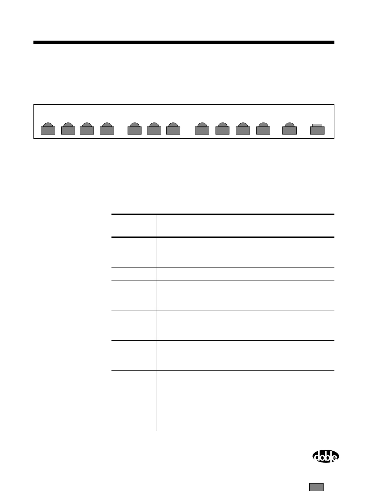
The CPU circuit board is installed in slot 3. It has twelve LEDs located at
the top of the CPU board (Figure 6.3), and one push button.
Figure 6.3 CPU Board Status Indicator LEDs and Push Button
• The LEDs indicate communication status (either RS-232 or
Ethernet) and are described in Table 6.2.
• The RESET push button activates a new power diagnostic cycle
when pressed.
LED3 LED2 LED1 LED0 LOCK LED3 LED2 LED1 LED0
STX2 SRX2 STX1 SRX1 ETX ERX CLSN
RESET
Table 6.2 CPU Board LED Indicators
CPU Board
LED
Indication
STX2
[D13]
RS-422 GPS transmit active.
Illuminates green during power up only, otherwise it is
OFF.
SRX2 RS-422 GPS receive active.
STX1
[D1]
RS-232 serial port transmit active.
Blinks red during RS-232 communication with the
controlling computer.
SRX1
[D2]
RS-232 serial port receive active.
Blinks red during RS-232 communication with the
controlling computer.
ETX
[D3]
Ethernet transmit active.
Blinks during Ethernet communication. This LED is
always OFF if no Ethernet cable is attached.
ERX
[D4]
Ethernet receive active.
Blinks during Ethernet communication. This LED is
always OFF if no Ethernet cable is attached.
CLSN
[D5]
Ethernet collision.
Blinks red during power up, and when no Ethernet
cable is attached.