F6000 Family of Power System Simulators User Guide
72A-1589 Rev. C 02/01 7-21
D
DD
D
R
RR
R
A
AA
A
F
FF
F
T
TT
T
3
33
3
/
//
/
5
55
5
/
//
/0
00
0
1
11
1
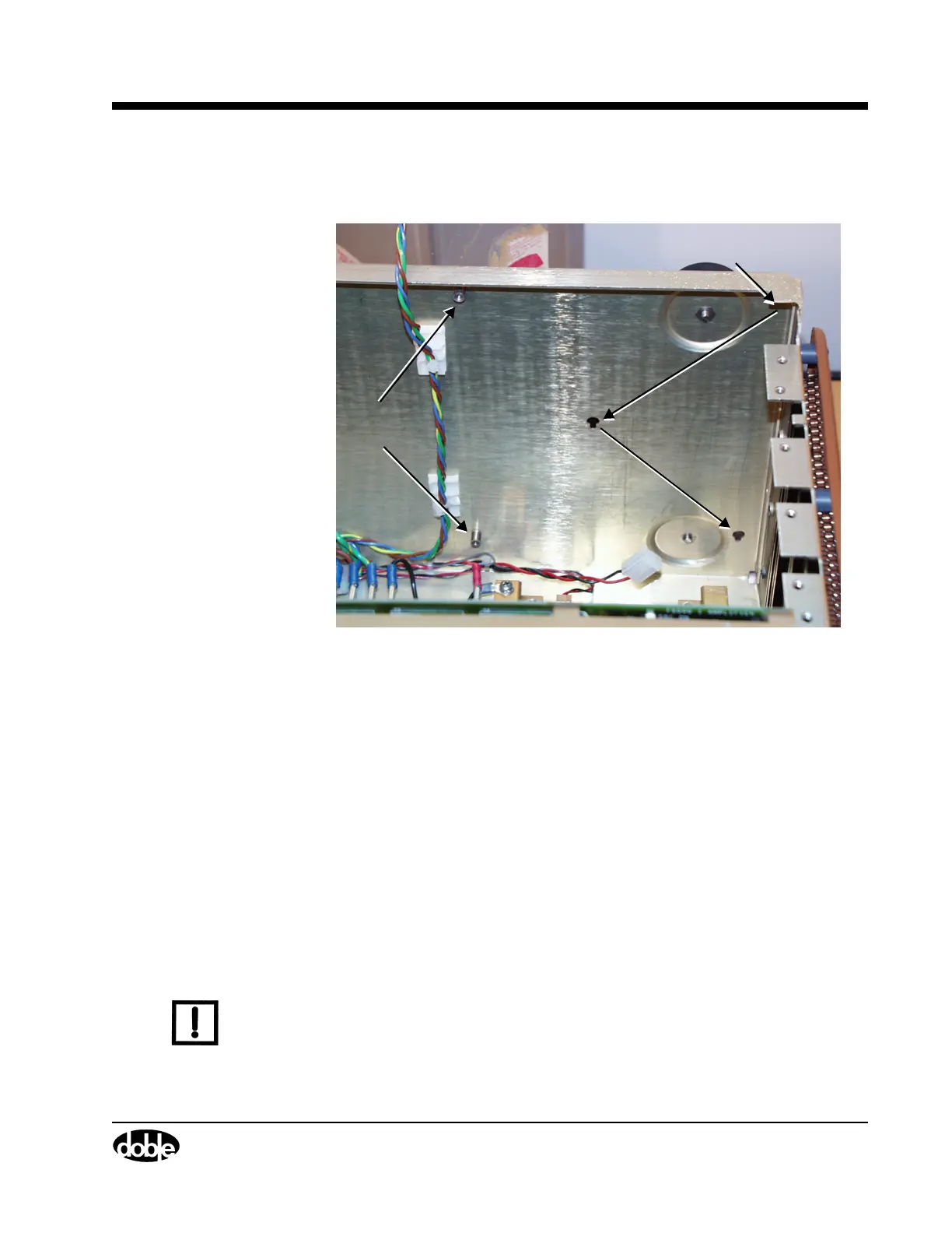
8. Use a Phillips head screwdriver to remove the screws in the upper
left-hand corner and the lower left-hand corner of the board.
Figure 7.13 Back Panel After Removal of Battery Simulator
9. Disconnect the wire from connector J4 in the upper right-hand corner
of the board.
10. Lift the circuit board up, then pull it out from the back panel.
Three teflon pins hold the battery simulator to the rear panel of the
instrument. These pins are located in the upper right-hand corner, the
center, and the lower right-hand corner of the circuit board. Work all
three pins loose from their sockets in the rear panel. Figure 7.13
shows the location of the pin sockets on the instrument chassis.
11. Disconnect the wire from connector J3 at the bottom of the board.
12. Lift the board out of the instrument.
13. To replace the battery simulator, reverse steps 1-11.
N
OTE
When replacing the Battery Simulator, reconnect wire W16 to the
power supply before seating the power supply in its slot, as it is difficult
to reach the wire connector after the power supply board is seated.
Use PIC00001a.tif on page 18.
Phillips Head
Screws Removed
Teflon Pin Sockets