F6000 Family of Power System Simulators User Guide
72A-1589 Rev. C 02/01 7-25
D
DD
D
R
RR
R
A
AA
A
F
FF
F
T
TT
T
3
33
3
/
//
/
5
55
5
/
//
/0
00
0
1
11
1
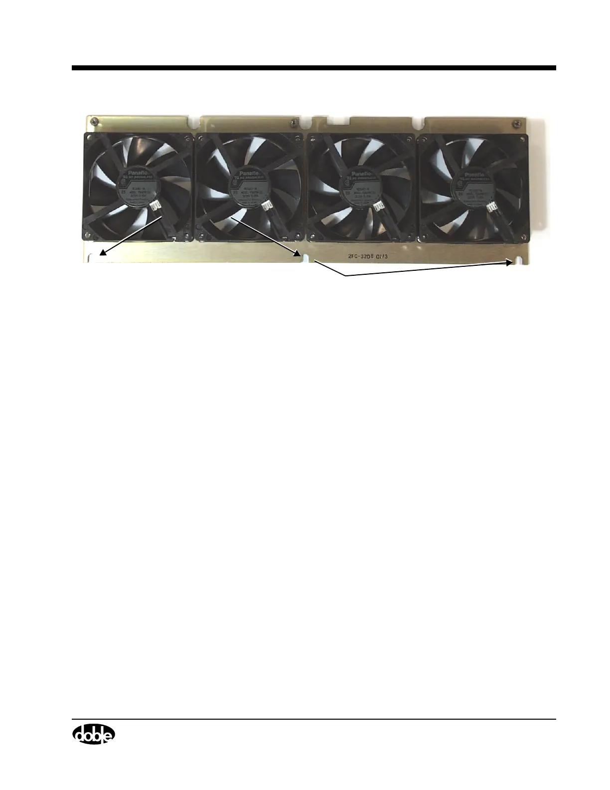
Figure 7.17 Cooling Fan Assembly
12. Pull the defective fan off of its supporting plate.
13. Install the replacement fan.
14. Secure the fan with the four hex nuts.
15. Reconnect the four wires, one to each fan.
16. Lower the fan assembly into the instrument until the bottom of the
assembly rests on the three spring-loaded supports attached to the
chassis.
Verify that the U-shaped indentations in the fan plate (Figure 7.17)
line up with the spring-loaded supports.
17. Push the fan assembly down onto the spring-loaded supports.
18. Replace the retaining bracket above the fan assembly.
19. Put the two Phillips head screws used to secure the bracket in their
original positions.
20. Replace the three Phillips head screws that fasten the top of the fan
assembly to the chassis.
21. Replace the side frame and protective screen with the eleven
hex-head screws.
U-Shaped
Indentations