Remove the Instrument Cover
7-2 72A-1589 Rev. C 02/01
D
DD
D
R
RR
R
A
AA
A
F
FF
F
T
TT
T
3
33
3
/
//
/
5
55
5
/
//
/0
00
0
1
11
1
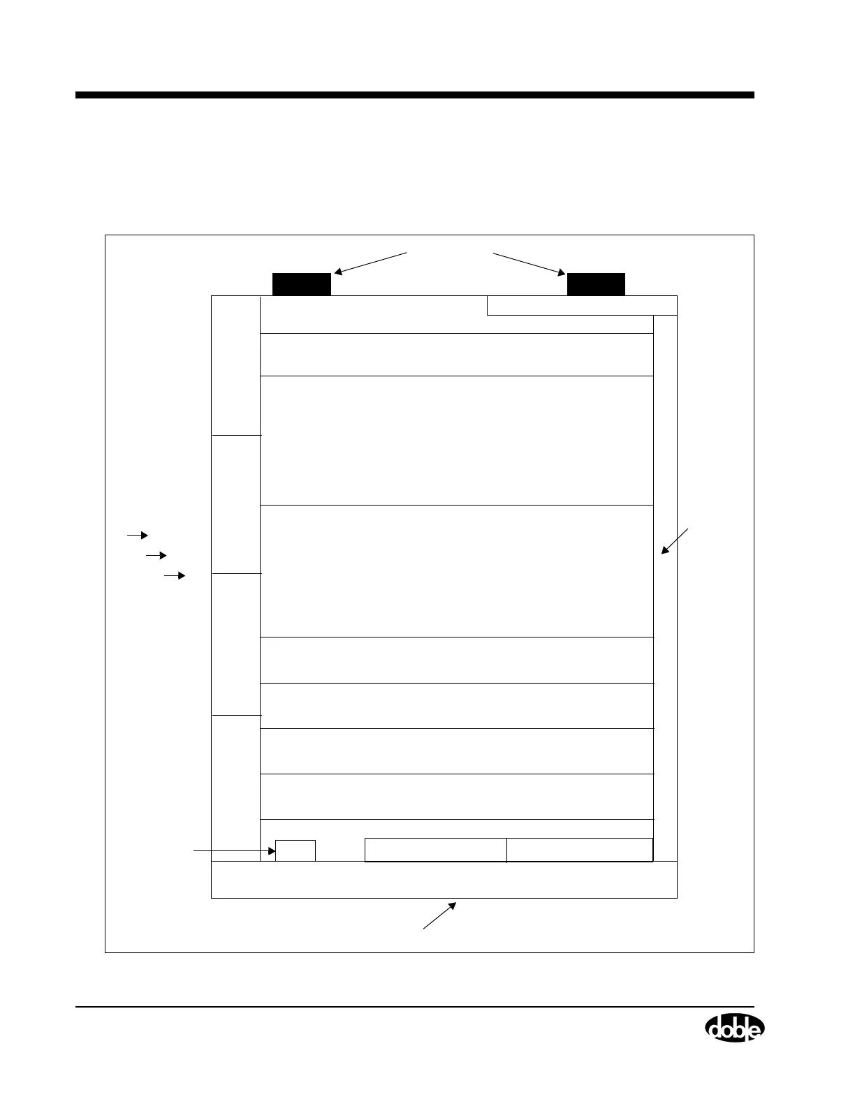
Remove the Instrument Cover
Remove the cover to access the replaceable components in the
Instrument. Figure 7.1 illustrates the location of these components.
Figure 7.1 Top View of the F6150 Instrument
Battery Simulator
Fan
Fan
Fan
Fan
Power Supply (Slot 11)
3 V/I Amplifiers (Slots 8, 9, and 10)
3 Current Amplifiers (Slot s 5, 6, and 7)
Analog I/O Board (Slot 4)
CPU Board (Slot 3)
Spare Slot (Slot 2)
Logic I/O Board (Slot 1)
Chassis Frame
Front Panel
Circuit Breaker
Output Terminal Board Communications Board
Retainer
Rail
Right Side
Left Side
Cooling Air
Intake
Front Panel
Rubber Feet
Back
#1
#2
#3
#4