Timers
4-24 72A-1589 Rev. C 02/01
D
DD
D
R
RR
R
A
AA
A
F
FF
F
T
TT
T
3
33
3
/
//
/
5
55
5
/
//
/0
00
0
1
11
1
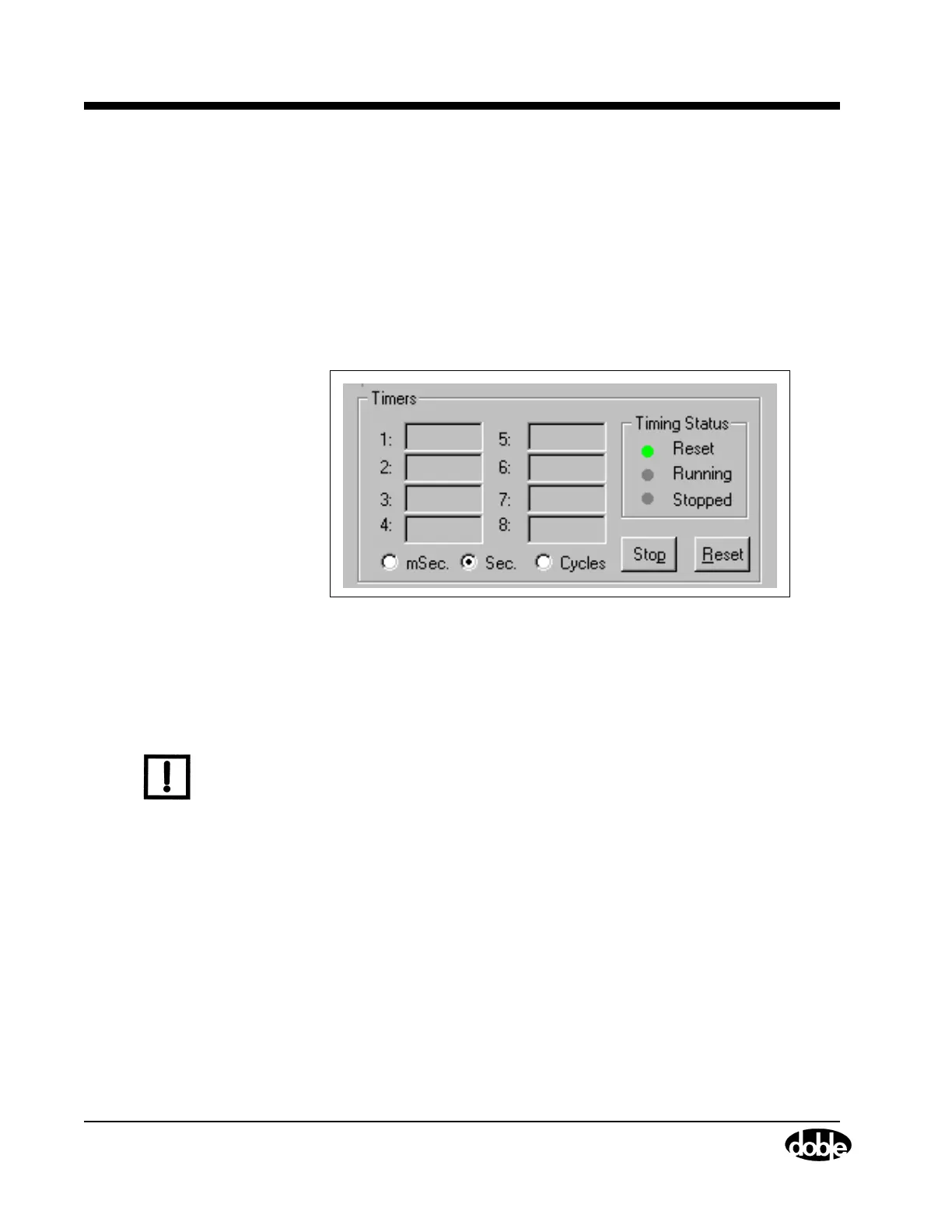
Timers
The Timers section contains readouts for eight timers (Figure 4.16).
Using logic inputs and logic outputs, time tests are possible for up to
eight separate events. The timers allow configuration of the logic inputs
and outputs for specific relays or for an entire protection scheme. For
example, use the timers to measure pickup and dropout times for relay
under tests. Use any timer with any source, any input or output, and any
trigger.
Figure 4.16 Timers Section
During a simple test of an overcurrent relay, the timer starts when the
source turns on and stops when the relay responds. The timer therefore
measures the response time of the relay.
N
OTE
Active timers have white fields. The initial reading for an active timer is
0.00 seconds. If the settings for a timer have not been defined in the
Timers tab, the readout for that timer is gray scaled. All of the timers
are inactive when Ramp mode is selected.