F6000 Family of Power System Simulators User Guide
72A-1589 Rev. C 02/01 F-15
D
DD
D
R
RR
R
A
AA
A
F
FF
F
T
TT
T
3
33
3
/
//
/
5
55
5
/
//
/0
00
0
1
11
1
2. Set the range to 75 V and amplitude to 75 V, connect the test
instruments as shown across Source VA and turn the source ON.
Verify that the amplitude is within limits and that the total harmonic
distortion (THD) is <2%.
3. Change the amplitude as shown in Table F.11.
Verify that the amplitude and distortion are within the limits.
4. Repeat step 3 for the 150 and 300 V range.
5. Repeat steps 2, 3, and 4 for Source VB and VC.
Table F.11 lists the specifications for the 150 VA Convertible Voltage
Source measurements.
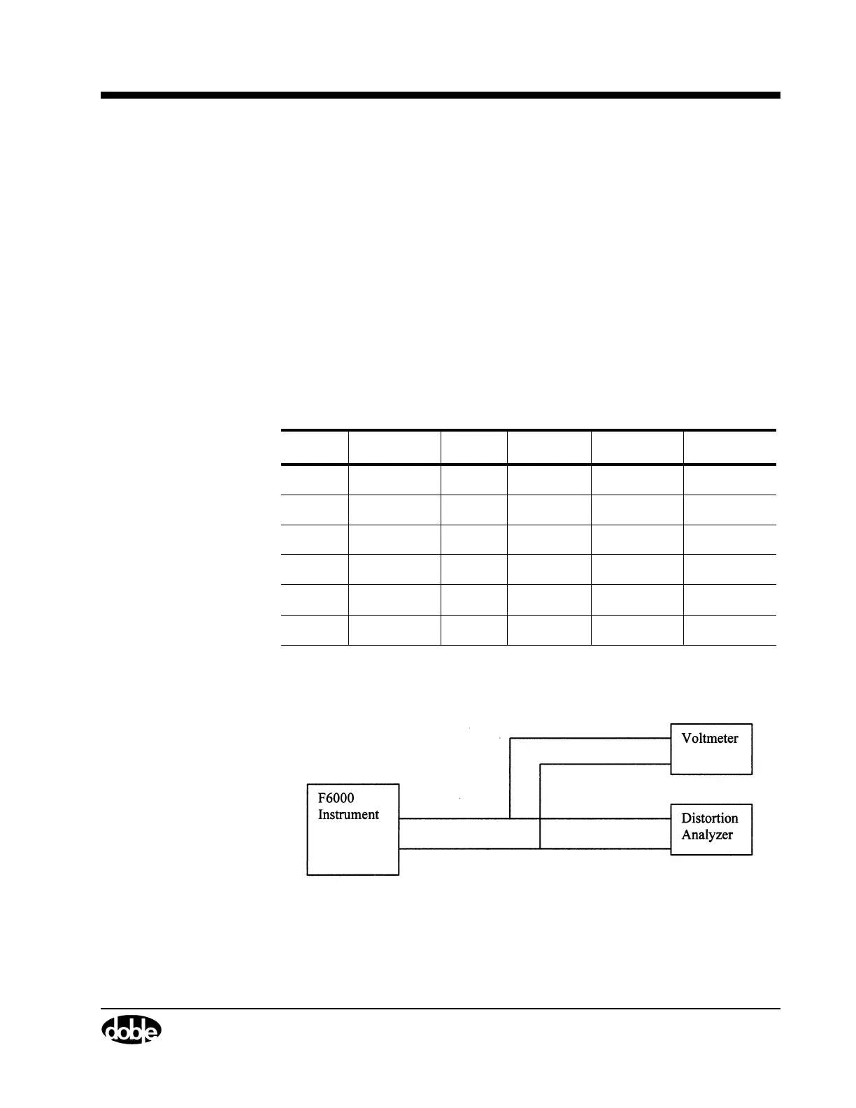
Figure F.10 shows
a typical setup for the 150 VA Convertible Voltage
Source measurements.
Figure F.10 150 VA Convertible Voltage Source Measurement
Table F.11 150 VA Convertible Voltage Source Specification
Range Max. Load Value Minimum Maximum Max. THD
75 V Open 75 V 74.8 V 75.2 V 2%
7.5 V 7.48 V 7.52 V 2%
150 V 150 V 149.6 V 150.5 V 2%
15 V 14.96 V 15.05 V 2%
300 V 300 V 299.1 V 300.9 V 2%
30 V 29.91 V 30.09 V 2%