F6000 Family of Power System Simulators User Guide
72A-1589 Rev. C 02/01 F-3
D
DD
D
R
RR
R
A
AA
A
F
FF
F
T
TT
T
3
33
3
/
//
/
5
55
5
/
//
/0
00
0
1
11
1
3. Change the amplitude as shown in Table F.2.
Verify that the amplitude and distortion are within the limits.
4. Repeat step 3 for the 15 A range.
5. Repeat steps 2, 3, and 4 for Source I2, I3, IR, IS, and IT.
N
OTE
The load, including wire and connections, must not exceed the Max.
Load specified in Table F.2.
Table F.2 lists the specifications for the 75 VA High Current Source
measurements. Minimum and maximum amplitudes are given in
amperes. When using a 4-terminal shunt, convert the values to the
appropriate voltages.
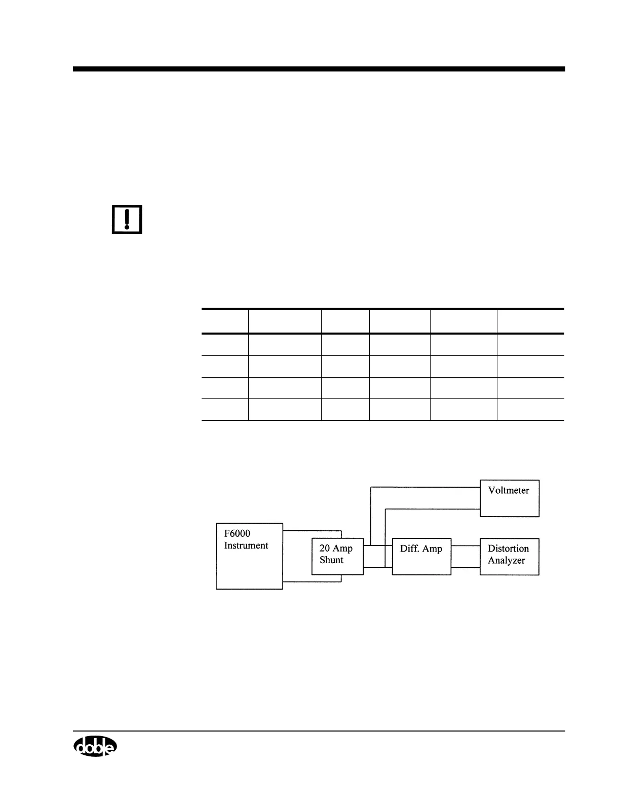
Figure F.1 shows a typical setup for 75 VA (right bank) Current and
Distortion measurement.
Figure F.1 75 VA High Current Source Measurement
Table F.2 75 VA High Current Source Specification
Range Max. Load Value Minimum Maximum Max. THD
7.5 A 1.333 Ohm 7.5 A 7.48 A 7.523 A 2%
0.75 A 0.748 A 0.7523 A 2%
15 A 0.333 Ohm 15.0 A 14.96 A 15.05 A 2%
1.5 A 1.496 A 1.505 A 2%