F6000 Family of Power System Simulators User Guide
72A-1589 Rev. C 02/01 F-11
D
DD
D
R
RR
R
A
AA
A
F
FF
F
T
TT
T
3
33
3
/
//
/
5
55
5
/
//
/0
00
0
1
11
1
2. Set the range to 1 A and amplitude to 1 A, connect an ammeter or
appropriate shunt across the Source I1 output terminals, (both I1
terminals must be connected to the ammeter or shunt) and turn the
source ON.
Verify that the amplitude is within limits and that the total harmonic
distortion (THD) is <2%.
3. Change the amplitude as shown in Table F.8.
Verify that the amplitude and distortion are within the limits.
4. Repeat step 3 for the 2 and 4 A range.
Table F.8 lists the specifications for the 300 VA Convertible Low Current
Source measurements. Minimum and maximum amplitudes are given in
amperes. When using a 4-terminal shunt, convert the values to the
appropriate voltages.
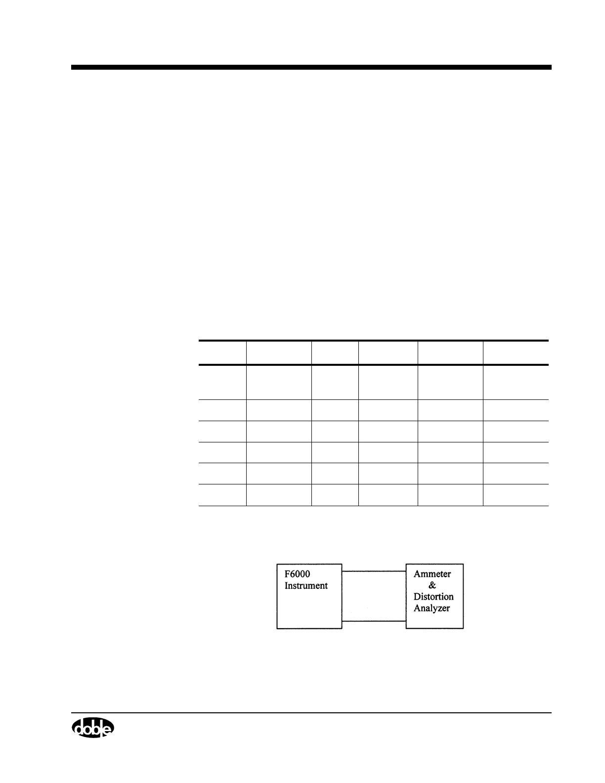
Figure F.7 shows
a typical setup for 300 VA Convertible Low Current and
Distortion measurements.
Figure F.7 300 VA Convertible Low Current Source Measurement
Table F.8 300 VA Convertible Low Current Source Specification
Range Max. Load Value Minimum Maximum Max. THD
1 A Ammeter /
Shunt
1.0 A 0.994 A 1.006 A 2%
0.1 A 0.0994 A 0.1006 A 2%
2 A 2.0 A 1.988 A 2.012 A 2%
0.2 A 0.1988 A 0.2012 A 2%
4 A 4.0 A 3.976 A 4.024 A 2%
0.4 A 0.3976 A 0.4024 A 2%