Verify the Replacement
7-26 72A-1589 Rev. C 02/01
D
DD
D
R
RR
R
A
AA
A
F
FF
F
T
TT
T
3
33
3
/
//
/
5
55
5
/
//
/0
00
0
1
11
1
Verify the Replacement
To determine whether the replacement procedure is successful:
1. Turn the instrument on.
2. Monitor the messages on the front panel as the instrument goes
through its startup sequence.
3. Check the status indicator light on the left side of each amplifier
board.
If the replacement is successful, the status indicator lights are green
and the error message on the front panel is cleared.
4. Repeat the test sequence that led to the error.
5. Check the instrument front panel for error messages.
6. Check the Control Panel in ProTesT for source errors.
Replaceable Components and Cables
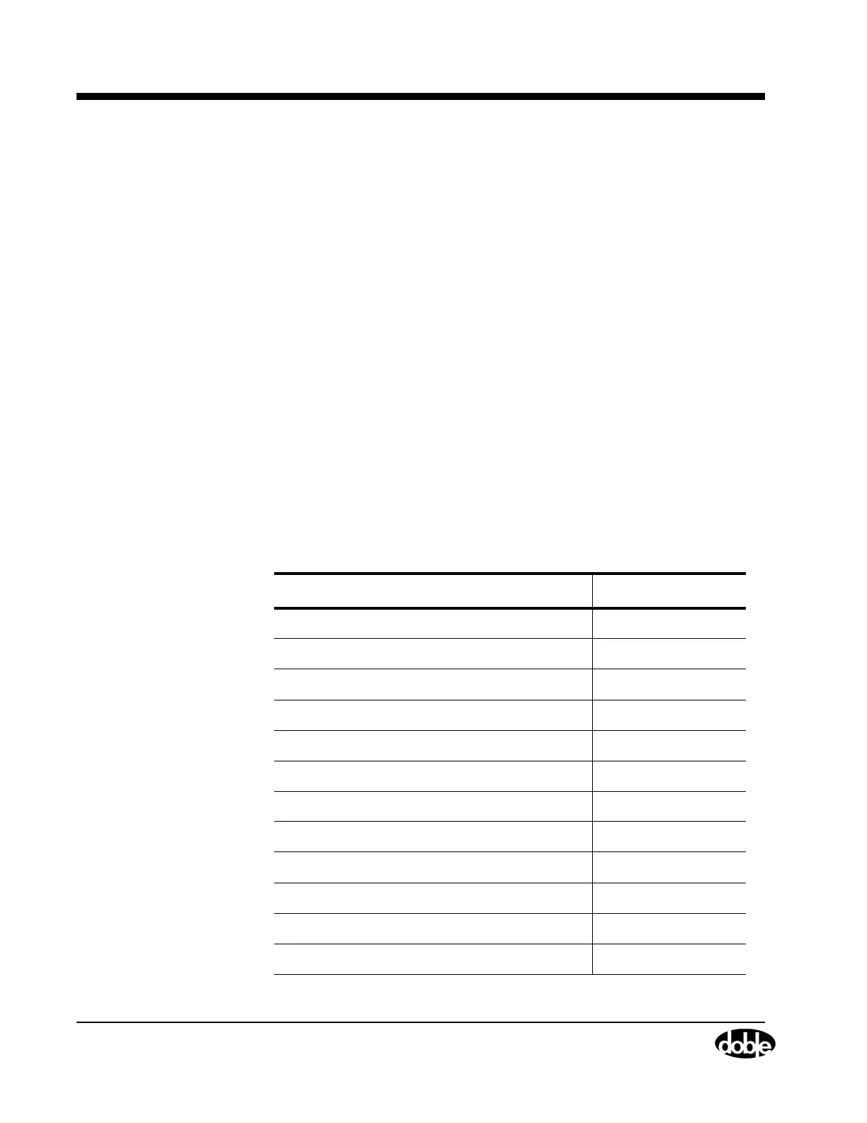
Table 7.4 lists the part numbers of field replaceable items.
Table 7.4 Field Replaceable Parts
Field Replaceable Part Part Number
Battery Simulator Board 04D-0598-01
CPU-F6 Board 04S-0670-01
Logic I/O Board 04S-0672-01
Analog I/O Board 04S-0673-01
F6 Communications Board 04S-0674-01
Output Terminal Board 04S-0675-01
115 V DC Power Supply Board 04S-0676-01
230 V DC Power Supply Board 04S-0676-02
I Amplifier Board 04S-0678-01
V/I Amplifier Board 04S-0679-01
DC Meter Board 04S-0680-01
Front Panel Assembly 03D-1356-01