Fault Rotate
5-18 72A-1589 Rev. C 02/01
D
DD
D
R
RR
R
A
AA
A
F
FF
F
T
TT
T
3
33
3
/
//
/
5
55
5
/
//
/0
00
0
1
11
1
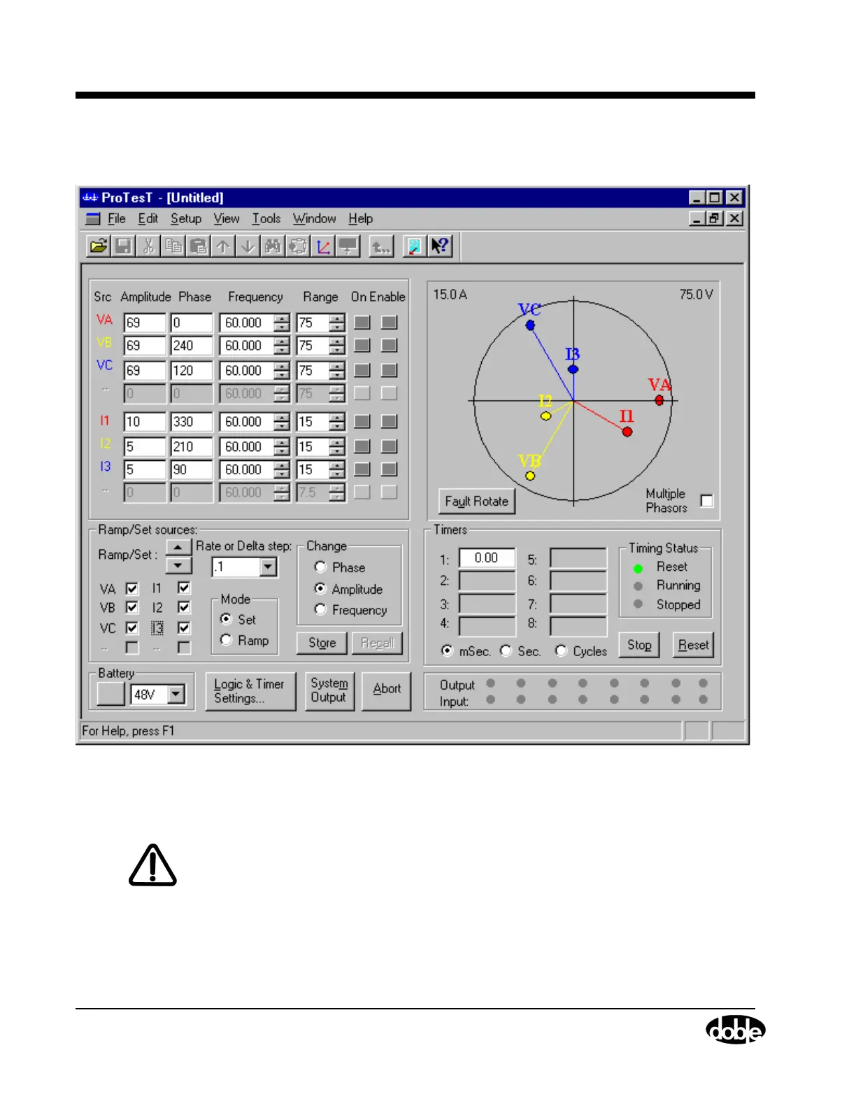
The Control Panel appears as it does in Figure 5.15.
Figure 5.15 Initial Setup for the Fault Rotate Test
6. Click the Enable button for current sources I1, I2, and I3.
WARNING The high intensity yellow LED flashes when the battery simulator or any
output source is on or enabled to indicate the potential for dangerous or
fatal voltages.
7. Click System Output to turn the current sources on.
When the relay responds, the indicator light for Input 1 turns green.
8. Click System Output to turn the current sources off.