Timers Tab
4-18 72A-1589 Rev. C 02/01
D
DD
D
R
RR
R
A
AA
A
F
FF
F
T
TT
T
3
33
3
/
//
/
5
55
5
/
//
/0
00
0
1
11
1
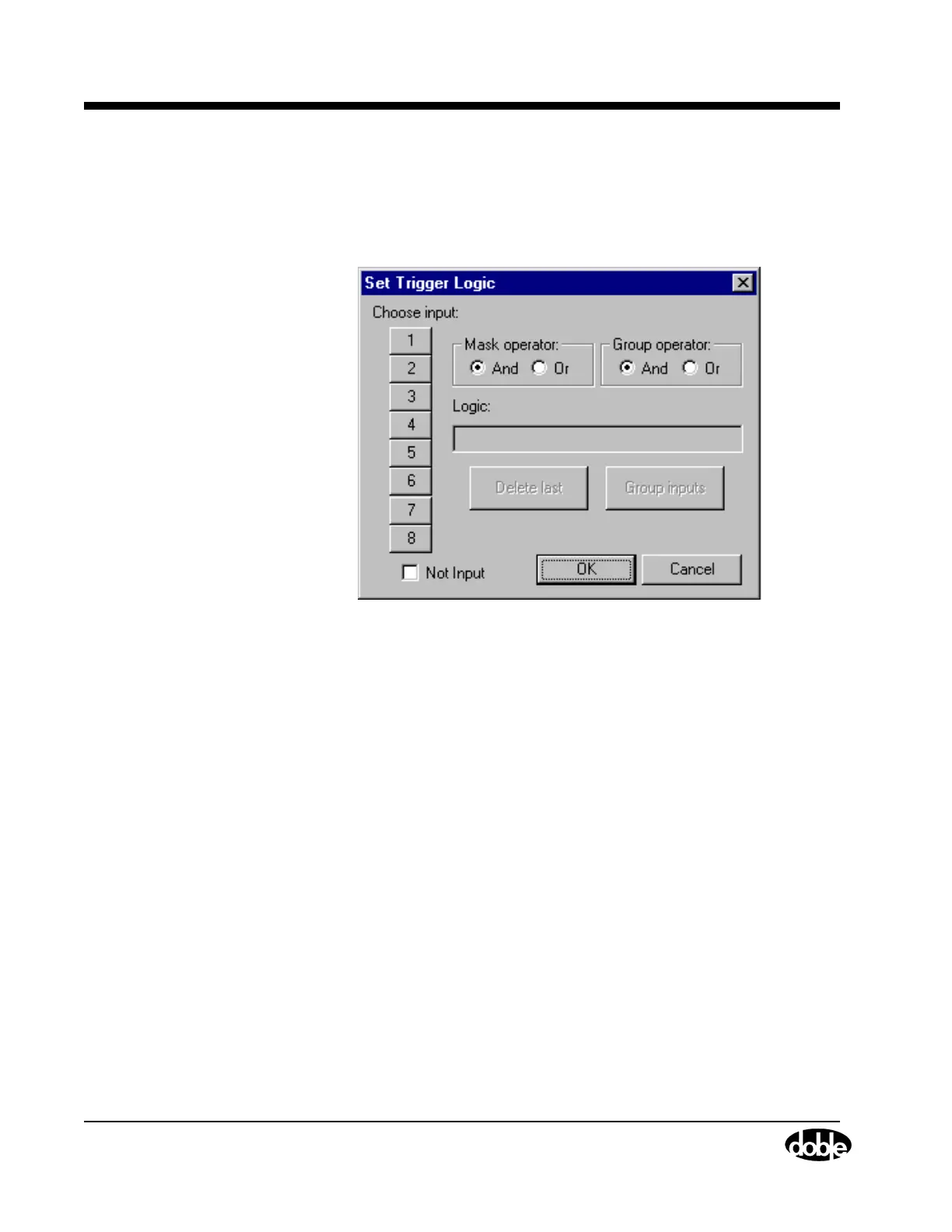
Click Set... for Trigger 1 in the Triggers display to open Set Trigger
Logic (Figure 4.12). Use the Set Trigger Logic display to select the inputs
needed to make the trigger true. For instance, click 1 under Choose input
to put In1 in the Logic field.
Figure 4.12 Set Trigger Logic
Multiple inputs can be configured as a trigger logic setting by using
Boolean operators with the inputs. The Boolean operators used are
And (*), Or (+), and Not (~). To put more than one input in the Logic
field, select And or Or under Mask Operator to connect them logically.
• Connecting the logic inputs with the And operator requires that
all the inputs be true to assert the trigger.
• Connecting the logic inputs with the Or operator requires that
any of the inputs be true to assert the trigger.
Click the Not Input checkbox to place a tilde (~) before a logic input. In
this case, the trigger is asserted when the logic input is not true.