F6000 Family of Power System Simulators User Guide
72A-1589 Rev. C 02/01 7-9
D
DD
D
R
RR
R
A
AA
A
F
FF
F
T
TT
T
3
33
3
/
//
/
5
55
5
/
//
/0
00
0
1
11
1
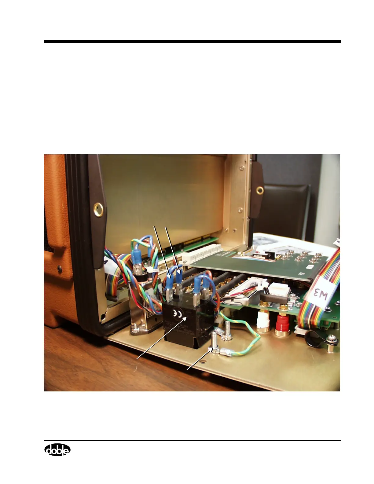
9. Disconnect the blue and brown AC wires that lead from the circuit
breaker back to the instrument.
• Grasp the blue insulation.
• Pull hard and work the connectors loose.
10. Use an open-ended wrench to remove the hex nut that secures the
chassis ground wire to the circuit breaker.
11. Disconnect the ground wire.
Figure 7.7 shows the location of the AC leads and the ground wire.
Figure 7.7 Wire Connections at the Front Panel Circuit Breaker
Chassis Ground Wire
Circuit Breaker
Blue and brown
AC wires