Input and Output Indicators
4-26 72A-1589 Rev. C 02/01
D
DD
D
R
RR
R
A
AA
A
F
FF
F
T
TT
T
3
33
3
/
//
/
5
55
5
/
//
/0
00
0
1
11
1
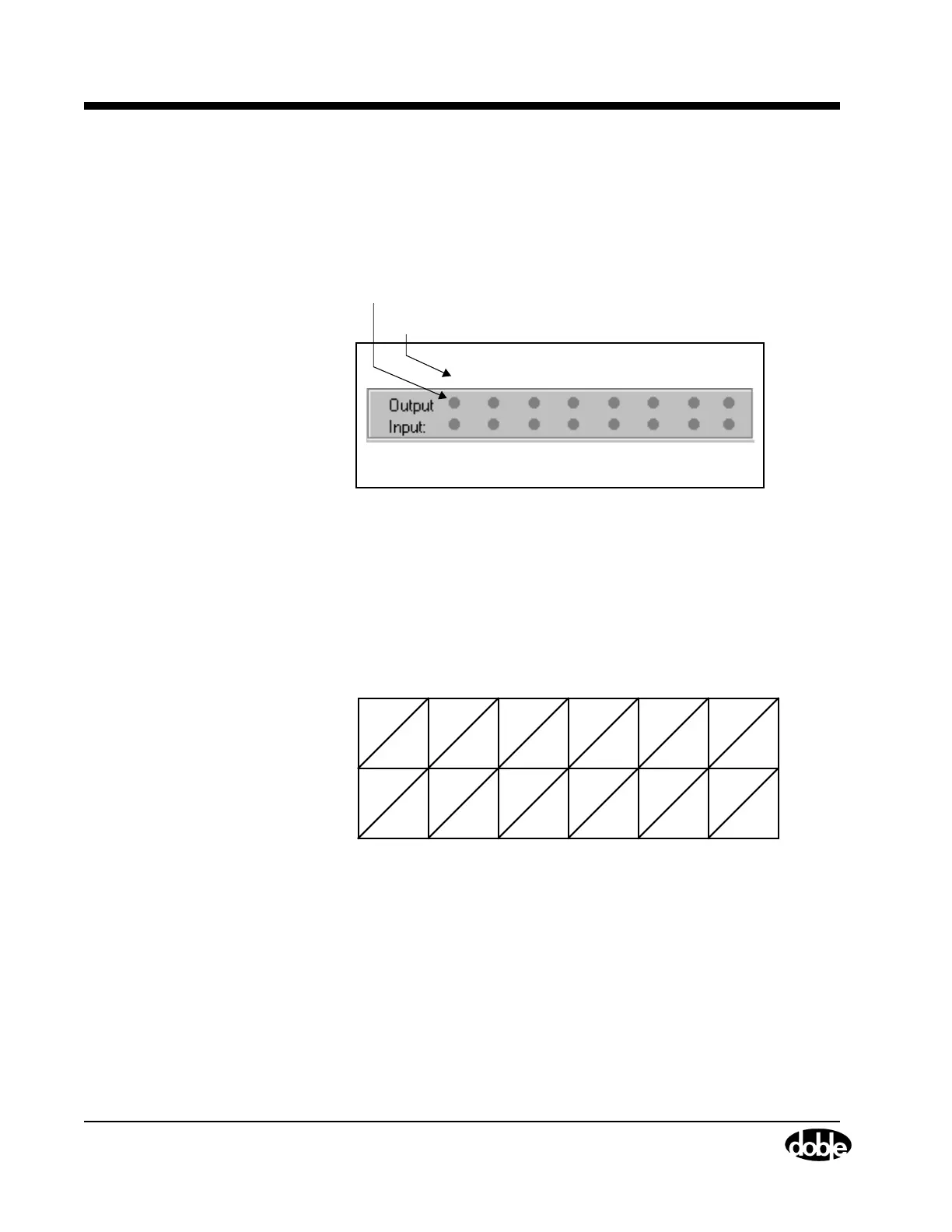
Input and Output Indicators
The Control Panel contains a status indicator for each logic output and
each logic input. The status indicators are numbered 1 through 8 from
left to right (Figure 4.17).
Figure 4.17 Output and Input Status Indicators
Each power source maps to one logic output and one logic input. The
mapping of sources to inputs and outputs depends on the source
configuration in effect. The mapping rule assigns the inputs and outputs
to voltage and current sources in ascending order first from left to right,
then from top to bottom. Figure 4.18, Figure 4.19, and Figure 4.20
illustrate how the rule works for three common source configurations.
Figure 4.18 Input and Output Indicators for Four Voltage Sources and
Four Current Sources
1 2 3 4 5 6 7 8
Output Number or Input Number
Status Indicators
V1 V2 V3
VN
I1 I2 I3
IN
1234 56
78
Sources
Indicators
Sources
Indicators