F6000 Family of Power System Simulators User Guide
72A-1589 Rev. C 02/01 4-27
D
DD
D
R
RR
R
A
AA
A
F
FF
F
T
TT
T
3
33
3
/
//
/
5
55
5
/
//
/0
00
0
1
11
1
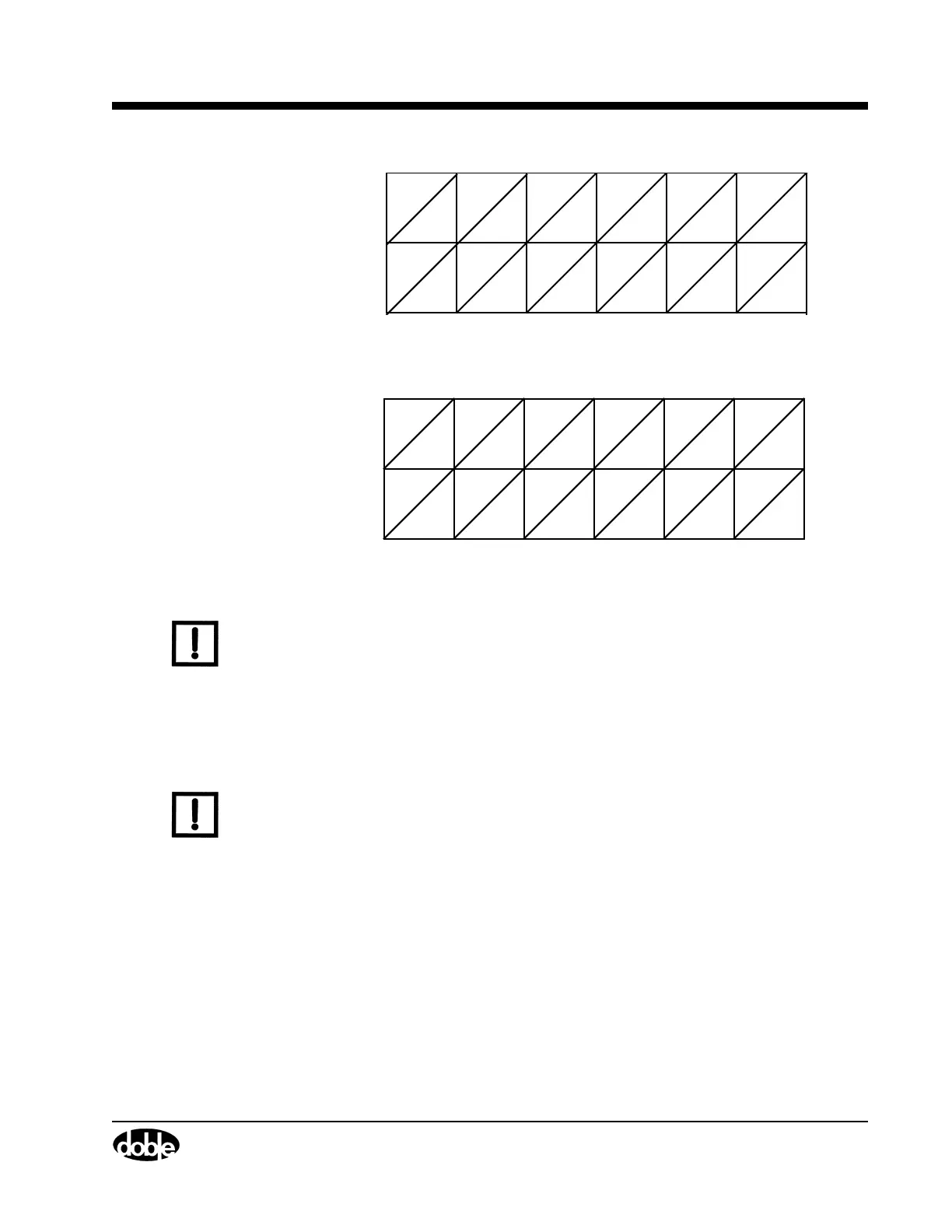
Figure 4.19 Input and Output Indicators for Three Voltage Sources
and Three Current Sources
Figure 4.20 Input and Output Indicators for Six Current Sources
N
OTE
If a ProTesT macro specifies source MA, the macro uses Input 1 and
Output 1.
A logic output gives the F6000 the ability to send out its own signal. It is
a logical relay that opens or closes its contacts when its associated source
goes on. The output is in its normal state when the source is off. A
normally open output contact closes when the source is turned on and its
corresponding status indicator illuminates.
N
OTE
The logic outputs can also be controlled in SSIMUL macro on a state to
state basis. In this macro, the logic outputs are associated with the
appropriate output sources (for example, VAI1). See the ProTesT Macro
Reference in the ProTesT User Guide (72A-1585).
A logic input is a signal that originates with the relay under test and is
sent to the instrument. Any trigger necessary to run a test can be
programmed as a logic input. See ”Define Triggers” on page 4-17 for
examples of how to use logic inputs in actual tests.
V1 V2 V3 I1 I2 I3
1234 56
Sources
Indicators
I1 I2 I3
123
6
I4
I5 I6
45
Sources
Indicators
Sources
Indicators