F6000 Family of Power System Simulators User Guide
72A-1589 Rev. C 02/01 7-5
D
DD
D
R
RR
R
A
AA
A
F
FF
F
T
TT
T
3
33
3
/
//
/
5
55
5
/
//
/0
00
0
1
11
1
Power Up and Perform a Visual Check
1. Attach the power cord to the instrument and turn it on.
2. Observe the LED lights on the left side of each amplifier board.
A green light indicates a good board. No light indicates a bad board.
When the sources are active, the green LED on the right side of an
amplifier board illuminates when that particular amplifier is
supplying power.
3. Verify, through the audible sound, that the four cooling fans are
operating.
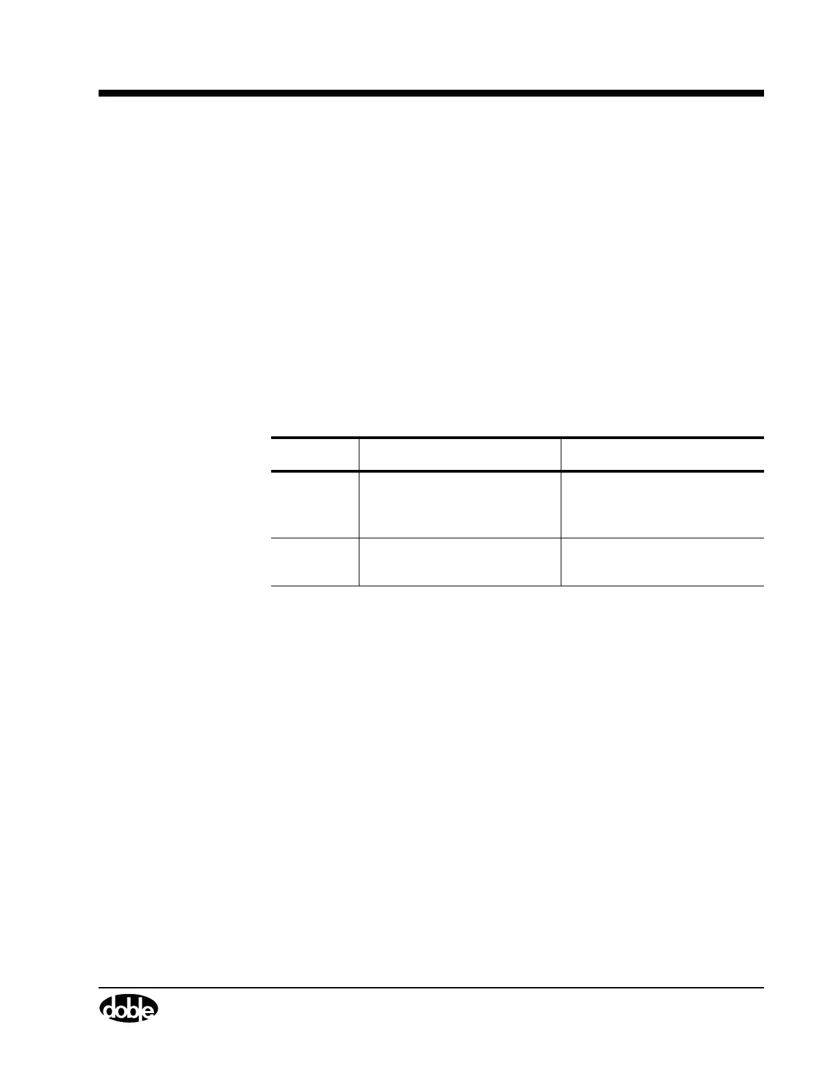
Table 7.1 summarizes the information conveyed by the status indicator
lights on the voltage and current amplifier boards.
Instrument Front Panel
To remove the front panel of the instrument, follow these steps:
1. Remove the 12 hex-head screws from the front panel.
2. Disconnect W2, W3, W4, W5, W6, and W7 from the Logic I/O
board, CPU board, and Analog I/O board.
3. With fingers resting on the inside surface of the front panel, grasp the
top of the black instrument frame.
4. Press the front panel out from the frame.
The front panel tilts forward and stops at about a 30° angle
(Figure 7.4).
Table 7.1 Status Indicator Lights on the Amplifier Boards
Indication 350V (Left Side) SRC ON (Right Side)
Green Instrument is turned on and
the amplifier is healthy.
The amplifier is supplying
power to an output
terminal at the front panel.
Not Lit The amplifier is faulty. The amplifier is not
supplying power.