F6000 Family of Power System Simulators User Guide
72A-1589 Rev. C 02/01 5-9
D
DD
D
R
RR
R
A
AA
A
F
FF
F
T
TT
T
3
33
3
/
//
/
5
55
5
/
//
/0
00
0
1
11
1
5. Click the Logic & Timer Settings button on the Control Panel
(Figure 5.6).
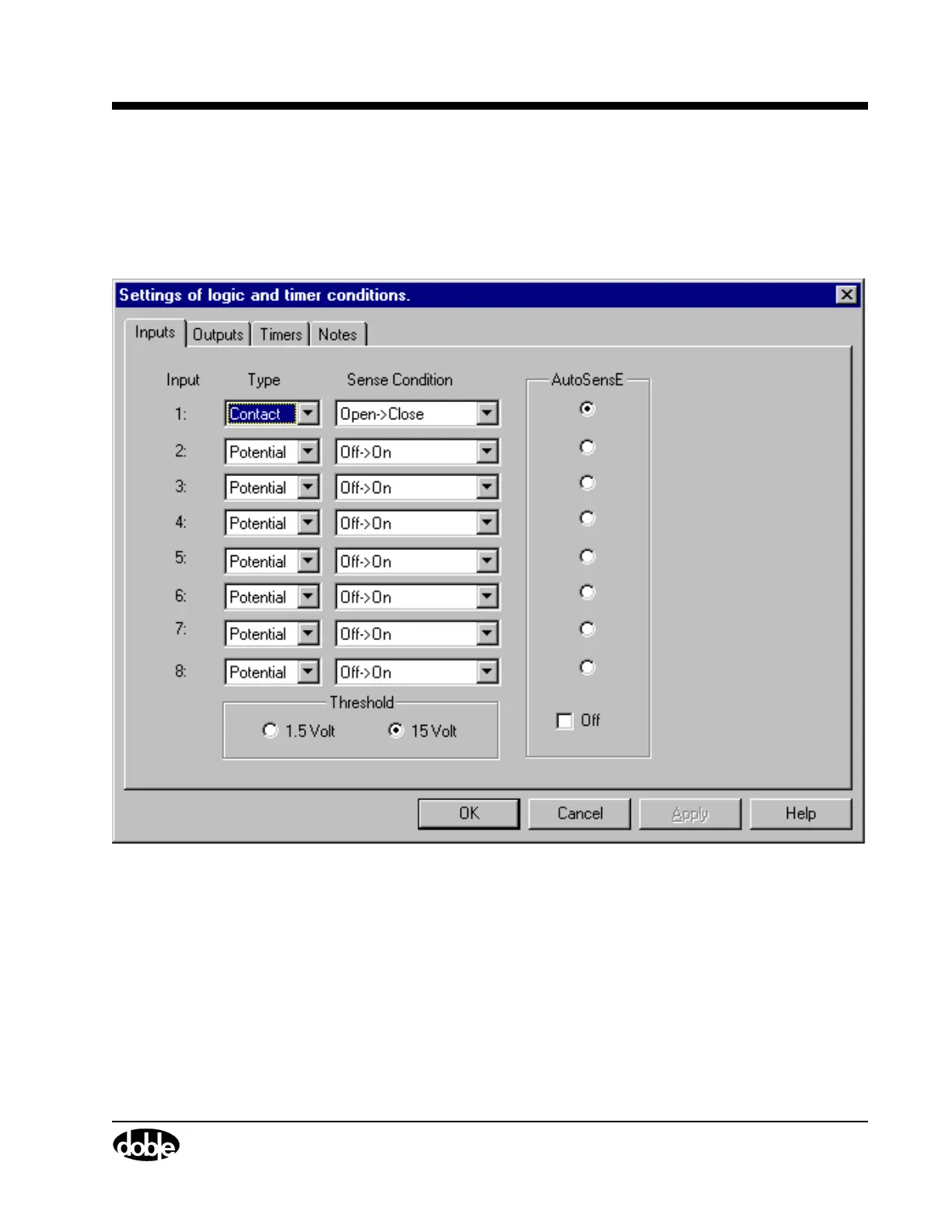
The Inputs tab of the Settings display appears (Figure 5.7). Use
Input 1 for this test.
Figure 5.7 Inputs Tab
6. Select Contact from the pick list under Type.
Leave Open
→
Close as the default Sense Condition.
The start and stop conditions for the timer are defined in the Timers
tab. The start condition for this test is true when the current source I1
turns on. The stop condition is true when the defined trigger is
asserted. The trigger is asserted when the relay under test responds.